Continue to Site

Welcome to our site!

Electro Tech is an online community (with over 170,000 members) who enjoy talking about and building electronic circuits, projects and gadgets. To participate you need to register. Registration is free. Click here to register now.

  • Welcome to our site! Electro Tech is an online community (with over 170,000 members) who enjoy talking about and building electronic circuits, projects and gadgets. To participate you need to register. Registration is free. Click here to register now.

Positive Terminal on Battery getting hot.

Status
Not open for further replies.

NCGrimbo

New Member
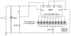
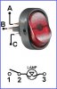
Hi all. I wanted to add an on/off switch to this from Radio Shack and connected the ground plug to the ground on the battery, the middle power plug to the positive on the battery, and the remaining plug went to power input for the circuit. IE: The switch sits between the battery and the 1M ohm resistor on the picture.

I have alegator clips on the battery terminals and when I run the circuit with the new switch, the clip on the negative terminal of the battery gets hot. I assume that this is not a good thing. Any hints on what is happening?

I'm a newbie to circuit designs so I'm not sure what is going wrong.

Thanks
 
I would presume the switch is intended for use in a car?, so it probably has a fairly high wattage bulb fitted?, so the high current for that could be getting your connections warm?.

Assuming everything is wired correctly?.

There's usually an extra connection on an illuminated switch for the bulb, try disconnecting that (so the bulb doesn't work), and see if it runs cool then.
 
first make sure u understand the wiring of the switch. second make sure your circuit is built correctly. third this circuit has a 6 volt battery on the diagram so make sure that u have the right voltage battery or u'll be roasting ur breafast toast on it if u get my meaning. fourth last but not least important: are the crocadile clips big enough and r they/it clean as this will cause extra resistance and so heating. also lake sure the battery is powerful enough.
 
your message and it's subject are telling two different things...
which terminal gets hot, positive or negative (or both)?
if only one is hot, it means you have loose connection. try soldering
wire or use proper automotive push-on terminals instead of aligator clips.
some aligators (specially smaller ones) are quite loose...
 
I just noticed the problem with the title. It's the negative post that is getting hot, not the positive post.

To answer some of the questions/suggestions:

1) The aligator clips are brand new and clean and crimped very tightly to the wires. They are approx. 1.5 inches long and hold the battery posts with a decent amount of friction.
2) The switch is the one linked above. The circuit works fine if the positive of the battery is connected to the middle post of the switch and the power post is connected to the circuit, but the light does not come on. (This was suggested to me to try). To get the light on, I connected the negaive post of the switch to the negative of the battery and it does light up, but the negative post gets hot. The switch has a diagram on it to show how to connect the posts.
3) The circuit works perfectly without the switch I am trying to add and nothing gets hot until I add the switch.
4) The battery is a 6volt battery from Radio Shack.
5) I think the switch is a car switch and I assumed that it was OK to use since it's rated at 12volts and the battery I am using is 6volts. I tried a 125V lighted switch, but the light would not come on.
 
what amperage is the battery (Ah) and what voltage and amperage/wattage is the bulb in the swith is it a lead battery or other ?
 
Beware of those different color croc-clips with wires.

The manufacturer does not solder the connections as they can't be seen inside the plastic covers. These are the ones I got.

This would make your life hell with the resultant intermittent connections.

Check every one you've got and solder them yourself.
 

Attachments

  • croc_clips.jpg
    croc_clips.jpg
    37.6 KB · Views: 677
According to http://support.radioshack.com/support_supplies/doc16/16582.htm, the switch is 30A 12V DC. Here are the specs as listed on that page:
Code:
Switch  (275-0712)            Specifications           Faxback Doc. # 16582

Model #:...........................................................R13-133B
Switching Function (Circuit):................................3P SPSP ON-OFF
Rating:..........................................................30A 12V DC
Contact Resistance:...........................................50 m/ohms Max
Insulation Resistance:...............................DC 500V 100 m/ohms Min
Voltage Breakdown:........................................AC 1500V 1 minute
Lamp Rating:...........................................DC 12V 50 mA +/- 10%

Here's the link to the battery: http://www.radioshack.com/product.a...y_name=CTLG_009_013_005_000&product_id=23-016. I don't see the amperage listed on that page, but the specs page for it says this:
Code:
Heavy-Duty Zinc-Chloride Battery
(230-0016)                 Specifications             Faxback Doc. # 40611

Battery Type: .............................................. Zinc Chloride
ANSI Designation: ................................................... 4 Fd
Suggested Current Range: ............................. 0-250 milli amperes
Voltage Taps: .................................................. -, +6 VDC
Terminals: ........................................................ Spring
Average Weight: ................................. 1 lb.- 6 oz. (623 grams)
Volume: .......................... 31 cubic inches (508 cubic centimeters)
Jacket: ............................................................ Metal
Dimensions (HWD): ....................... 4-3/8 x 2-11/16 x 2-11/16 Inches
                                                 (169.16 x 68.2 x 68.2 mm)

Estimated Average Service at 70 Degrees F (21.1 Degrees C)

                                                     Hours to
                  Starting                 _______Cutoff Voltage________
                   Drains        Load     |                             |
Schedule       (milliamperes)   (Ohms)    3.6 V       3.0 V        2.6 V

30 Min/Hr.           667           9      11.0         15.0         17.5
8 Hrs/Day

0.25 Sec/Sec         100          60       470
24 Hrs/Day

NOTE:  Typical Discharge Profile Test: 9 Ohms, 30 Min/Hr, 8 Hrs/Day

Specifications are typical; individual units might vary. Specifications are
subject to change and improvement without notice.

The clips I got were not connected to a wire but I've got them attached to wire and the connection is not loose.

Does this help?
 
I can't tell which connection is which so I posted the switch and its electrical connections here.

Hopefully someone can tell you which terminal is which. The point is terminal 3 should be connected to 0V(negative terminal of battery). Terminal 2 to your circuit and terminal 1 to +12V battery via fuse.

If you own a multimeter, test the resistance between each terminal and one other. If that resistance changes from zero to infinity with operation of the switch then you have found terminals 1 & 2. If the meter reading is not zero and not changing with switch operation, then you have found 2 & 3.

If you are still in doubt, you will have to ask the supplier for switch connection.

Don't ever forget to use a suitable fuse at the positive connection to the battery.
 

Attachments

  • rocker.jpg
    rocker.jpg
    17.8 KB · Views: 600
pin 1 to + of battery pin 2 to the positive of the circuit and pin 3 to the negative of the battery but pray how r u gonna power the 12 V bulb in the switch from the 6 volt battery
 
Thunderchild said:
pin 1 to + of battery pin 2 to the positive of the circuit and pin 3 to the negative of the battery

I know someone will said that. OK, so which terminal is 1? A,B or C?

Thunderchild said:
but pray how r u gonna power the 12 V bulb in the switch from the 6 volt battery

Like any other light bulb inside a torch with worn out batteries.
 
well what is the problem then if the circuit works ok without the switch and with it there is a problem then either the switch is connected wrong or your battery is two small to handle the power as i have not got ur project here to look at tht is all i can say it is up to u to verify which is the problem. as a last resort open the switch and check the bulb setup is not faulty as it can happen and how about going to the top and finding out what all this gear is using in amps by connecting a multimeter in series with the set up ? just a thought
 
if u lack knowledge as to the connections then get a multimeter and start by identifying the switch terminals and then with the aid of a battery check which one is the ligh cmon it's not that hard just play around with it. i often use old stuff and have to do this it is great fault finding experience
 
eblc1388 said:
I just noticed that you have the connection diagram. Please posts it here.

According to the diagram on the side of the switch:

Top connector is called Power (A in your picture)
Middle connector is called Load (B in your picture)
Bottom connector is called Ground. (C in your picture)
 
Thunderchild said:
pin 1 to + of battery pin 2 to the positive of the circuit and pin 3 to the negative of the battery but pray how r u gonna power the 12 V bulb in the switch from the 6 volt battery

This is what I did origonally. This is what causes the the negative pole on the battery to get hot. :)
 
The filiament of the lightbulb has a positive temp coefficient. Is it possible that it draws a hundred milliamps or more at 6V, when it is rated at only 50mA at 12V? :?:

Use a switch with an LED in it. :lol:
 
i bet that circuit will run on 12 volts so if u realy like the switch or rather u realy want the bulb to come on the use 12 volts and next time DO make sure u get the right switch. u could just use a led (or 6 volt bulb) on the current design and forget the light in the switch
 
Well, I really want the lighted switches to work, so I'll try the circuit with a 12V batter and see what happens.
 
The LED currents will be higher with a 12V battery but the 470 ohm resistors will limit the current to a safe level.
The 4017 sequencer circuit doesn't need ten 470 ohm resistors, only one output is active at any time so a single resistor will be fine.
 

Attachments

  • led_sequencer.png
    led_sequencer.png
    14.2 KB · Views: 263
Status
Not open for further replies.

Latest threads

New Articles From Microcontroller Tips

Back
Top