SABorn
New Member
I do feel like i am bashing my head against the wall here.
1) a SCR is a latching device with DC power and can not be turned off via the gate, if so something is wrong.
2) the leds on the output (K) side of the SCR Can not make the gate sensitive or turn the SCR on, if so something is wrong.
3) the SCR can only switch on when + power (5v+) is applied to the gate, when power is removed from the gate or the gate goes negative the scr will remain latched on, until the load is removed from the output (K) or the supply is disconnected (A) then the scr will switch off and remain off till the gate is activated again with 5v+.
So yes the leds on the output of the scr can hold the scr latched on ONLY after the scr has received a 5v+ signal to the gate and not before.
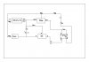
Please try this test circuit to help solve the problem, note i have removed the 15 ohm resister and placed a 2200 ohm (2K2) resistor in the gate supply from the opto, as well as a 330 ohm resistor in the led supply to the opto.
Also note i have also removed 1 led from the output side of the SCR (K) as the 2nd led allowed a current path to supply the first led, the existing led should be on when the SCR is off, and the led will go off when the SCR is on.
Wire it EXACTLY as i have drawn it and it should all work the way these components are meant to.
Please do this test to help us help you.
Pete.
1) a SCR is a latching device with DC power and can not be turned off via the gate, if so something is wrong.
2) the leds on the output (K) side of the SCR Can not make the gate sensitive or turn the SCR on, if so something is wrong.
3) the SCR can only switch on when + power (5v+) is applied to the gate, when power is removed from the gate or the gate goes negative the scr will remain latched on, until the load is removed from the output (K) or the supply is disconnected (A) then the scr will switch off and remain off till the gate is activated again with 5v+.
So yes the leds on the output of the scr can hold the scr latched on ONLY after the scr has received a 5v+ signal to the gate and not before.
Please try this test circuit to help solve the problem, note i have removed the 15 ohm resister and placed a 2200 ohm (2K2) resistor in the gate supply from the opto, as well as a 330 ohm resistor in the led supply to the opto.
Also note i have also removed 1 led from the output side of the SCR (K) as the 2nd led allowed a current path to supply the first led, the existing led should be on when the SCR is off, and the led will go off when the SCR is on.
Wire it EXACTLY as i have drawn it and it should all work the way these components are meant to.
Please do this test to help us help you.
Pete.