Continue to Site

Welcome to our site!

Electro Tech is an online community (with over 170,000 members) who enjoy talking about and building electronic circuits, projects and gadgets. To participate you need to register. Registration is free. Click here to register now.

  • Welcome to our site! Electro Tech is an online community (with over 170,000 members) who enjoy talking about and building electronic circuits, projects and gadgets. To participate you need to register. Registration is free. Click here to register now.

Pocket PC Car Charger

Status
Not open for further replies.

AlainB

Member
I have an Axim X51V pda. I had no luck in finding a suitable car charger.

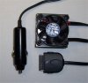
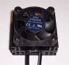
So, since the voltage of the wall charger is 5.25 volts I made a charger out of a 7805, wired the typical way with 2 small capacitors. It is charging the battery fine, just a bit slower than the wall charger. I had to put the 7805 on a hudge heat sink and I added a fan because after one hour of charging, even the heat sink get quite hot, maybe 60-80 C.

When the battery is fully charged the amber light on top of the PDA turn green and the recharging state indicate 100%.

I suppose it is not the best way of recharging a battery but what are the risks? Could the battery get overcharged or is it the PDA that control how the battery is charged?

Is there other things that could happen?

On my next trip in Asia, if it is not too risky, I will plug this charger on the battery of the 110cc Suzuki that I will drive to use my PDA as a GPS and a compass. The mopped will be rented so I don't expect his battery to be in mint condition so the 7805 will probably see some variations of the input voltage.

Alain
 

Attachments

  • Axim 12v charger 1.jpg
    Axim 12v charger 1.jpg
    94.3 KB · Views: 530
  • Axim 12v charger 2.jpg
    Axim 12v charger 2.jpg
    105.5 KB · Views: 407
  • Axim Pocket PC.jpg
    Axim Pocket PC.jpg
    289 KB · Views: 766
Last edited:
The PDA will control the charging so what you have done is OK for that.

If you want it to generate less heat, you need a Buck Regulator. You can get the regulator to run cooler with a bigger heatsink or by putting a resistor of about 5 ohms, 10 W in series with the input of the regulator.

You can adjust the 7805 to give about 5.25 V by putting a schotky diode in series with the ground leg. However, the slow charging might be due to the 7805 going into thermal shut down.
 
Thanks!

With the fan on, the 7805 and the heat sink are not getting hot a bit. Not even warm.

When charging and the PDA is in use the rate is about from 0.2 to 0.5 A. At power up it may go as high as 0.75 amp but this is the highest that I had seen. When the PDA is off and the battery is fully charged, the charging rate drop to 0.006A some kind of floating charge I suppose. So you are right. It is the PDA that is controlling the charging.

Alain
 
Last edited:
It would probably not work. 500 mA is not enough to charge this PDA. At least not while using it. I tried numerous things before building the charger. I ordered an USB charger from Hong Kong and it is was not working even plugged on a 12VDC to usb converter. I tried a 1 Amp. car charger and it was not working too.

The wall charger is rated at 5 volts, 2 amp. It is outputing 5.25 volts when not plugged to the PDA. The L7805C that I am using is rated at 1.5 amp.

As I said, I tried many things but to make it short, I found out that the gage of the wire used is very important. The unit I got from Hong Kong was not working, even when connected to a computer power supply (5 volts, many amps). Changing the cable for an heavier gage one made it work.

After consulting the datasheet of the L7805C I found out that the 0.006 amp. that I was talking on my previous post is the quiescent current of the regulator, not a floating charge used by the PDA.

I made a mistake and I wonder if it is of any consequence. The L7805C datasheet specify a 0.33 uF and a 0.1 uF capacitors to be used but I used instead a 0.22 uF and a 0.1 uF. This is what was recommend in an other datasheet that I consulted for a 7805 before building the charger.

Anyway, I am happy with this not so efficient charger. What is important is that it is working and besides, I like it's "kool" look.:)

Alain

axim-12v-charger-3-jpg.34996
 

Attachments

  • Axim 12v charger 3.jpg
    Axim 12v charger 3.jpg
    77.9 KB · Views: 1,089
Last edited:
AlainB.

We coudl all suggest various buck regulator chips, which would do the job of stepping down (noisey and variable) automotive voltage to the voltage you require. But then you would need all the parts, the inductor, and probably a half decent PCB.

I would suggest ebay. You can get pretty damn good 10-20W switch-mode modules with half decent efficiency for a few dollars.

**broken link removed**

I have 5, they're pretty good up to a couple of amps.
 
Thanks for that.

I have a previous unanswered question. What could be the effect of using a 0.22 uF instead of a 0.33 uF on that situation? As far as i know, this capacitor will prevent the 7805 from oscillating but will a 0.22 uF cap. be close enough?
 
Thanks for that.
I have a previous unanswered question. What could be the effect of using a 0.22 uF instead of a 0.33 uF on that situation? As far as i know, this capacitor will prevent the 7805 from oscillating but will a 0.22 uF cap. be close enough?
Yes! a 0.22 uF cap value is OK,too.
 
Status
Not open for further replies.

Latest threads

New Articles From Microcontroller Tips

Back
Top