Continue to Site

Welcome to our site!

Electro Tech is an online community (with over 170,000 members) who enjoy talking about and building electronic circuits, projects and gadgets. To participate you need to register. Registration is free. Click here to register now.

  • Welcome to our site! Electro Tech is an online community (with over 170,000 members) who enjoy talking about and building electronic circuits, projects and gadgets. To participate you need to register. Registration is free. Click here to register now.

PNP Transistor Drive

Status
Not open for further replies.

Suraj143

Active Member
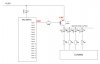
I want to increase the supply voltage to the LEDs (without damaging the PIC) to get some descent brightness in my LED matrix 16 X 32 design.Here how I'm going to do.
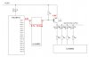
Will the transistors get OFF 5.5-4.8 = 0.7V still available in base :(

Due to saturation drop of ULN2803 (1V Loss) I'm going to supply this wasted voltage from source side. Is it ok?
Roughly a single column LED will take 64mA peak current. When multiplexed at 1/16th rate, the Average will be 4mA per LED.
 

Attachments

  • PNP Bias.JPG
    PNP Bias.JPG
    49.3 KB · Views: 223
The transistor won't turn fully off. However, if you put a diode (or two) in series with the base resistor then the base will be at 5.5V and be off.

Mike.
 
I'd also add that you really need a resistor between base and emitter as well, to ensure the transistor turns OFF - it's always good practice, and particularly so in this case where any slight leakage in the proposed diodes will prevent the transistor turning OFF fully.
 
Could a P channel mosfet be used that has a gate threshold voltage around -4V. The supply could then be 8V and the mosfet would be off with the gate at 5V. Not sure how fast the switching will be/needs to be. Or would a darlington be a better choice?

Mike.
 
With a darlington on each end of the LED circuit, after the two saturation voltages there might not be enough voltage left for some white or blue LEDs.

ak
 
Could a P channel mosfet be used that has a gate threshold voltage around -4V. The supply could then be 8V and the mosfet would be off with the gate at 5V. Not sure how fast the switching will be/needs to be. Or would a darlington be a better choice?

If you're going for a darlington configuration, better to use an NPN at the bottom, and a PNP at the top - no issues then with voltage, and plenty of drive for the transistors. For that matter, you could use another ULN2803 at the bottom (as the NPN's), and a row of PNP's at the top
 
Personally, I favor the UDN2981 series of source drivers. You can jack up the supply voltage as high as you want (up to 35V or so), to get the drive you need. With all 8 pins sourcing power, you can still drive about 125mA per pin, lots of current for LEDs. Individual pins can handle 500mA, but the chip is somewhat limited to a total current of about 1A. Datasheet shows duty cycle vs pins counts at various currents. Below 125mA per pin, you can drive all 8 pins
Being TTL compatible, I use these with a small PIC to drive 24V relays directly. I put small (10k) pull-downs on the input pins to prevent triggering due to any noise. For more drive, you can parallel matching inputs and outputs together
There are more modern equivalent types of chips out there as well, search for "source drivers". No need for extra transistors....
Not sure if this fits your design or not, but worth considering...
 
Jacking the supply up by 0.5V is cleaver!
But that leaves T1 almost/barely on.
By using two 330R resistors it now turns on at 1.3V not 0.65.
The driving IC has about 1 volt loss. Here is much of the problem. Change to a MOSFET or a NPN transistor and you will gain about 0.8V.
120281
 
Ok, Thanks everybody for the suggestions.

Earlier I replaced the bottom ULN2803 with NPN transistors & it worked nicely with a descent brightness.

The problem with that design is you need a base resistor (2 soldering pads) & a NPN transistor (3 soldering pads) altogether 5pads X 32 columns = 160 pads which takes long time to solder the PCBs & also the PCB size also bigger than I expected.

That's why I changed it to a ULN package.But it has lower brightness due to voltage loss :(
 
No, sorry for the confusion - a SECOND ULN2803, feeding the PNP's at the top.

I have a problem on this.If I drive the top PNPs by another ULN to ground isn't that 1V Saturation drop cause to maintain the Base Emitter junction always biased ON PNPs?
 

Attachments

  • PNP Bias 2.JPG
    PNP Bias 2.JPG
    58.1 KB · Views: 202
The ULN is open collector so when it's off there is no base current.

Mike.
 
In the post #12 schematic, you need a base current limiting resistor in series between each PNP base and its 2803 driver.

ak
 
Status
Not open for further replies.

Latest threads

New Articles From Microcontroller Tips

Back
Top