Continue to Site

Welcome to our site!

Electro Tech is an online community (with over 170,000 members) who enjoy talking about and building electronic circuits, projects and gadgets. To participate you need to register. Registration is free. Click here to register now.

  • Welcome to our site! Electro Tech is an online community (with over 170,000 members) who enjoy talking about and building electronic circuits, projects and gadgets. To participate you need to register. Registration is free. Click here to register now.

Please! need to reverse polarity for 12v motor

Status
Not open for further replies.

standry

New Member
I am a beginner and i have this project.

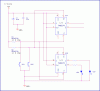
I need help creating a system to reverse polarity on the motor in order to rotate CW then CCW at designated spots (top and bottom positions) .

12v aa battery powered motor with threaded shaft that needs rotate and go a certain distance, then verse direction and rotate to its start postion. I have it currently wired with a 3 position on/off/on manual switch. I need any help offered to have this motor rotate CW to its top position then rotate CCW to the bottom(start) position using relays/sensors/auto swithing/whatever.

the entire device will be enclosed.

Just not sure which path to take???

Thanks in advance.
 
Question:

The motor will run a distance turning a lead screw until it reaches a point. Then reverse and run back to its start position. Once the motor has done that will it repeat?

If the motor is to repeat and just continue to run out and in over and over again there are several ways to do it. One method would be to use a few SPDT micro switches as stops and have them drive relays that latch.

Motor polarity could also be controlled by an H Bridge. How much current does the motor draw? Using a H Bridge would likely be a good way to go with this. Limit switches toggle flip flops that drive the H Bridge.

Again, how much current? What did you have in mind?

Ron
 
Thanks for the reply.

To answer your first comment, yes once power is applied lead screw reaches point and reverses then repeats.

The motor i am using is rated as follows, 6Vdc, 180mA, 180 RPM @ 12Vdc, 180 mA (no-load). I am using 12v

I'll have to research the differences between the 2 suggestions you offered. Any additional info would be greatly appreciated.

Thanks again
 
OK and at 180 RPM you will need to know the screw pitch (how many threads for a distance be it inch or CM or whatever unit of measure) and that will give you your traversing travel speed.

Ron
 
If you want a very simple circuit that allows the motor to traverse the full length of the screwed rod then reverse, here is the circuit:
**broken link removed**

Simply connect two limit switches (in parallel) in place of the push switch and connect the output to a relay.
The motor will start in one direction and then reverse when the limit switch is activated.
 
I think there are simpler solutions.

A DPDT relay can be used with a normally open and normally closed of microswitch and a couple of diodes.
Motor h-bridge lim sw osc1.PNG

Alternatively, if you want solid state, four transistors can be made into an h-bridge which will double as a bistable flop-flop.

The trouble with this idea is the direction won't be predictable at switch on and will depend on which transistors are fastest and have the higher gain. My simulation program said that all the transistors will turn on simultaneously at power on, even when I tried altering the gains but going on previous experiance with bistables, I think this is unlikely. If it's a problem, add a capacitor across one of the switches: a 1µF electrolytic should do.

Motor h-bridge lim sw osc2.PNG

The second circuit can be made to self oscillate by adding capacitors to form an astable multivibrator. This isn't a practical approach since the capacitors will need to be huge and we want the frequency to depend on the speed of the motor. This could be used as a loud piezo driver.

EDIT:
Added 1µF capacitor.
 
Last edited:
I would think about using just a simple flip flop similar to the attached drawing. Pins 5 & 6 of the 7474 would toggle a H Bridge. Since the 7474 is a dual Flip Flop the second half is used just to drive FWD and REV LEDs. I left out the LED series resistance as it would depend on the actual circuit voltage. Additionally the power pins are redundant on each half of the 7474. Anyway, given the choice I would likely use a flip flop but any number of ways to do it would work.

Ron
 

Attachments

  • 7474 toggle.gif
    7474 toggle.gif
    17.9 KB · Views: 1,908
You don't seem convinced on the transistor bistable idea?

I simulated it again in LTSpice and it too said that all of the transistors will turn on when power is first applied, even if the gains are different but the higher gain transistors do have higher currents, as I'd expect. In real life I'd imagine that the transistors carrying the highest current would heat up, causing them to conduct more, leading to a safe, stable state with the motor running in either one direction or the other but as I've not built the circuit I wouldn't put it to chance, it's possible all the transistors will meltdown.

Fortunately, there's a very simple solution: connect a small capacitor across one of the bottom transistors to ensure the motor always starts in one direction only; this is probably desirable anyway so I'd strongly recommend it, so much so, I've added it to the original schematic.

An IC flip-flop would probably be safer in that it's been proven to work, although it's a lot of extra parts, especially as this is running from 12V so a regulator is required.

I'd suggest trying my idea with a dummy load resistor, try 220R, and temporarily put a resistor in series with the whole circuit to protect the transistor, if the worst happens, try 15R. Then when you've got it working, replace the dummy load with the motor and remove the series resistor and replace with a 500mA fuse, yes it's always a good idea to fuse circuits like this.

EDIT:
I forgot to say, I simulated it with Crocodile Technology (a kid's program) beofore. I'd say that as it now works perfectly with two simulators, it seems pretty convincing.
 
Last edited:
:)

You don't seem convinced on the transistor bistable idea?

I don't doubt for a moment it would work Hero and likely work just fine. When I have needed to do this (reversing a motor) I have generally used relays or a flip flop if I was using a H Bridge. Actually the bi-stable transistor approach is pretty slick. I just tossed out there how I generally go about it.

Ron
 
Status
Not open for further replies.

Latest threads

New Articles From Microcontroller Tips

Back
Top