Electro Tech is an online community (with over 170,000 members) who enjoy talking about and building electronic circuits, projects and gadgets. To participate you need to register. Registration is free. Click here to register now.
Welcome to our site! Electro Tech is an online community (with over 170,000 members) who enjoy talking about and building electronic circuits, projects and gadgets. To participate you need to register. Registration is free. Click here to register now.
Please help me with my project. Any one can please help me to have electronic layout of a 12V alternating light flasher. I used to have a thesis and I badly needed it. Thanks!
This is a project for your degree? What is your degree?
If your degree is in electrical engineering, surely you have *some* knowledge with which to start this project? Some ideas of how to do this? And hopefully you can ask more specific questions than "give me the entire answer" ?
Do you know what an astable multivibrator is? 555 timer IC? Time constant of an RC circuit?
This could be a trivially easy project, or you could make it more complex (as engineer types are wont to do...)
The main idea was motorized vehicle does'nt have hazard and i just realized that motorized vehicle must have too by intalling it a alternating flasher that serve as a hazard light. 12V light and 12V input. The speed of alternating light 1 sec per blink.. Thanks for the reply!
I'm taking course computer technician, basic electronics is one fof my course subject this semister. I dont have to use it in any commercial purposes. please help me to have that diagram or circuit layout. please....
yes they have an emergency flasher, but my project is a two alternating light and not two syncronized light like the cars has. This link below is too close with my project but I need to have a 12-volt power source and 12-volt light output.
Thanks to those who responce, luv you!
Did they teach Ohm's law? And Kirchoff's voltage law? I hope so. I hope you were taking notes, too
You'll need to apply both laws to each LED in selecting R4 and R5 and you'll need to know the forward voltage drop for your LEDs as well as their max continuous current (usually 20-30mA for the small LEDs).
Do you understand how this circuit works? The 555 alternately grounds the center point between the LEDs (sinking current from the top LED) and supplies voltage (sourcing current for the bottom LED).
This is assuming you want to use LEDs. If you want to use lamps, you'll need to design a circuit that can drive them, by replacing the R4/R5/D1/D2 with the appropriate circuitry (you could use a relay, MOSFET, or BJT) to allow the 555 to source/sink current below it's max ratings yet drive the lamps at the appropriate voltage/current.
As for the components around the 555, there are tons of tutorials on how to set up an astable multivibrator with that IC, and how to select the frequency, although, R3 in that circuit is a potentiometer so frequency is adjustable in the circuit. Up to you to figure out if you need to change anything on the 555 to work at 12V at the frequency you desire.
You *did* go to school to learn electronics, after all
hehehe... actually, I wouldn't be, given how much (or rather, how little) I knew about designing circuits coming out of a computer engineering* bachelor's program
I really have no idea on how the components works or any degree they are telling. I'm a computer technician that has a electronic subject as a background. Please help me to have that kind of circuit.
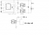
but here is the basic circuit you want. may not be the best but should work.
may need to recalculate some of the resistors.
a mosfet might be better but this is simple IMO
remove the two LEDs that I took out from original circuit.
all they do is indicate the flasher is working.
the 555 can run on 12v but then you need to maybe do some resistor changing (R4 and R5) for starters.
a single relay could be used (DPDT) then only one opticoupler is needed.
Biochem/electrostatics R&D
Greetings; melvinspeed21
this lab cannot understand why people with electronic knowledge are not inclined to help fellow seekers and the planet at large to progress through space and time.
contact radio shack, buy the $10 book on 555 timer's
aquire several 12vdc led's, study time of aprox five hours, one hour of R&D, two hours of experimental play with several 555 timers. will demand the proper answers herein. this is why I do my research before I post. you will find that there are few techno paths that post due to the lack of [service to others]
in this time frame.
you will find, if you do your own research and design your own circuit is simple and very rewarding. the half breed has spoken!
I assume
seeing how he is attempting to power a 555 off of another 555 output.
he may have smoked a 555 seeing how a 555 is only capable of outputting a max of 200ma.
true the 555 dosn't need 200ma to operate UNTIL it has to drive two other 555's
lets not forget, applying power to a 555 resets the internal timers of the 555 thus it won't operate as expected.
I posted a link that discussed just this subject and it has a schematic on how to eliminate the problems of reset on power up.
wonder if he even looked at the lnk or the recent schematic I posted.
Can lead a horse to water but can't make it drink.
This site uses cookies to help personalise content, tailor your experience and to keep you logged in if you register.
By continuing to use this site, you are consenting to our use of cookies.

 )
)