Continue to Site

Welcome to our site!

Electro Tech is an online community (with over 170,000 members) who enjoy talking about and building electronic circuits, projects and gadgets. To participate you need to register. Registration is free. Click here to register now.

  • Welcome to our site! Electro Tech is an online community (with over 170,000 members) who enjoy talking about and building electronic circuits, projects and gadgets. To participate you need to register. Registration is free. Click here to register now.

Please comment on my LED driver.

Status
Not open for further replies.
Here is how I would do it: The Sim shows the LED current and LED Vf as a function of the emitter resistor. This method draws less current from the port pin, and has a more constant current through the LED if the 5V supply changes than the circuit the OP posted.

The collector current is nearly the same as the emitter current. Since the transistor is operated as an emitter follower, it is not saturated, and the base current is tiny compared to the common-emitter configuration.

Hey Mike.

Could you explain why this Emitter Follower has its IC more constant when VF of the LED changes?
 
Hi,


I assume you want to turn the LED on and off with the transistor. If not, you probably dont need a transistor and most circuits like this operate with just a single resistor based on the max allowable current and the min current required for acceptable brightness.

If you really want to regulate the average current through the LED then you can insert a resistor in the emitter circuit rather than collector circuit and when you turn the LED on with the uC pin you can measure the current through the LED with an AD port. That will give you an estimate of the peak current through the LED and from that you can calculate the required duty cycle to keep the LED at full brightness at all times regardless of the forward voltage or power supply variation.
For example, if you use a 50 ohm resistor and you measure 1v across it with the AD port that means you have a peak current of 1/50=20ma so you need to keep the transistor turned on all the time, but say you measure 2v across it then that means you have a peak current of 2/50=40ma so you need to pulse the output pin at a 50 percent duty cycle to get an average current of 20ma.
The duty cycle is computed from:
D=Irequired/Ipeak
where D ranges from 0 to 1 (which represents 0 to 100 percent).

Since Ipeak is measured with the sense resistor Rs, Ipeak=Vrs/Rs so the duty cycle calculation becomes:
D=Rs*Irequired/Vrs
where Rs is the emitter resistor and Vrs is the voltage measured across it when the transistor is on. Of course the measurement should be done within a reasonably fast time period so the LED doesnt get overpowered. The most likely way of doing this would be to measure it during the normal 'on' time of the transistor and do the calculation and then adjust the duty cycle. At start up, the duty cycle would be set to some low value like 0.1 (10 percent) just to get the first measurement.
If you wanted to you could also subtract an estimate of the base current from the peak current measurement but you most likely dont need that kind of accuracy for a simple LED. For example if you dont subtract you end up with about 19.5ma LED current and if you do subtract you get very close to 20ma LED current. For a 2N2222A and 5k base resistor and 5v supply voltage the base current is about 580uA using a 50 ohm emitter sense resistor.
 
Last edited:
Hey Mike.

Could you explain why this Emitter Follower has its IC more constant when VF of the LED changes?

Because the current through the LED is determined by [(Port Pin High voltage) - Bve]/Re.
 
Mike and MrAl, Thank you very much!

I understand now that using the emitter resistor, makes IC to be dependent only on variations of VBE(ON) and the value of PORT(HIGH) (~3.3V), and not on VF of the LED, or VCC (5V) of the power supply, right?

so:
Re = (3.3V - V(R_Base) - VBE) / 20mA. (Where I take VBE as 0.65V).

How do you pick the value of R_Base?
 
The constant current sink transistor is an emitter-follower so it doesn't need a series base resistor.


Hello there audioguru,


I think you should look at this again :)

Normally we may not use a base resistor with an emitter follower but this isnt, strictly speaking, an emitter follower, it's still a common emitter amplifier just with an emitter resistor. For example, if you short the base to +5v the collector will not be able to get much below about 5v minus maybe 0.5v or so, which means the collector would only be able to get down to about 4.5 volts.

The value of the base resistor is adjusted according to the gain of the transistor and the LED current. Since the LED current can go as high as 30ma perhaps, 0.030 divided by 100 comes out to 0.0003 amps, which is 300ua. The base voltage will be 30ma times the emitter resistor which is 1.5v plus the base emitter diode drop of about 0.7, which brings us to a total of 2.2 volts at the base, and 5 minus 2.2 is 2.8 volts, and 2.8 divided by 0.0003 comes out to 9333 ohms, but with a little less transistor gain we would be in trouble so make it half of that or around 4.7k. You can go lower, but the lower you go the more accuracy you loose unless you subtract the base current from the emitter current measurement as before. Since 4.7k will lead to about 600ua you would subtract that, and if you want to go as low as 2.2k then you have to subtract about twice that or 1.2ma. If you dont subtract you wont loose a heck of a lot of accuracy, just a little which is probably just fine.
So the base resistor Rb is:
Rb=(Vcc-Vbe-Ve)/Ib
and
Ib=(Ic/Beta)
and of course
Ic=I_Led
and probably a better estimate for Beta is 50, using a 2N2222A or similar NPN transistor.

Note that is for the top end LED current, where you intend to regulate via PWM from the uC chip. If you dont intend to regulate this way, then you should really put all the current limiting into the LED resistor and use the transistor as a simple switch.
BTW you may have to make the emitter resistor lower, like 40 ohms. The idea is to make sure you can get the LED current level you want with the required range of LED voltage, unless you dont regulate and then you should do it with a collector resistor instead.
 
Last edited:
You cannot buy any transistor with a certain beta. Beta is a range of numbers and you get whatever is available.

The constant current sink transistor has a reference voltage at its base, not a current. So the series base resistor is not needed.
 
Hi MrAl, thanks a lot for such a great response.

When you refer to regulation:
unless you dont regulate and then you should do it with a collector resistor instead.
you mean that the Port's output voltage (which is 3.3V by the way) is regulated?
 
You cannot buy any transistor with a certain beta. Beta is a range of numbers and you get whatever is available.

The constant current sink transistor has a reference voltage at its base, not a current. So the series base resistor is not needed.

Thanks Audioguro.
I must say that it sounds logical, as the input of this LED driver is voltage and not current.
 
Hi MrAl, thanks a lot for such a great response.

When you refer to regulation:

you mean that the Port's output voltage (which is 3.3V by the way) is regulated?


Hi,


Well no, i meant that you have two choices here:
1. Regulate the LED current
2. Dont regulate the LED current

If you regulate then you do it one way (emtter resistor) but if you dont regulate then you do it another way (collector resistor, and estimate the current).
 
You cannot buy any transistor with a certain beta. Beta is a range of numbers and you get whatever is available.

The constant current sink transistor has a reference voltage at its base, not a current. So the series base resistor is not needed.


Hi there audioguru,


Surely you didnt think i meant that you have to go out an buy a transistor with an exact beta of 100 or 50 or something, did you? What i was saying is that we estimate the beta using perhaps a typical value and go from there to estimate the other circuit values. Once we do this, we can explore the circuit operation by using several values of Beta and see if the circuit operation will remain stable for the range of possible real life Betas we might encounter.

About the series base resistor...
I asked you to look at this again because this isnt your typical voltage follower. A voltage follower has as its input a voltage at the base, and as its output it has a voltage at the emitter (im sure you are well aware of this). To put it another way, we would be using a voltage to control another voltage.
With this actual circuit however, we are going to want to be able to control a current with a voltage, ie control the current though the LED (which also is in the collector circuit not the emitter circuit BTW) with the voltage coming out of the microcontroller chip pin. Not only is this not the same type of control, but it's not even the same type of circuit. Because the load is in the collector circuit we have a common emitter amplifier here, not a voltage follower. If you want to however, you can look at it as a voltage follower anyway and reckon the voltage across the emitter resistor as being converted into a current and thus it still controls the LED current, however, because of the other constraints of the circuit we can not apply a voltage (such as +5v with Vcc=+5v for example) to the base directly because then that would not allow enough collector voltage freedom. We'd be restricting the range of collector voltage to about +4.5v to +5v which just isnt enough range to get this circuit to work with the LED in the collector circuit.
To say it another way, if we apply +5v to the base directly then the emitter voltage goes up to about 4.3v and that means even with a saturation voltage of 0.000 volts we'd only be able to get the collector to go down as low as 4.3v, and with a 2v Vf LED that would not be enough voltage to get it to light up.
With a base resistor however, the uC pin goes to +5v but the emitter voltage only goes as high as dictated by the other circuit parameters and components, which will be much much lower, and that will allow a saturated transistor to put enough voltage across the LED to get it to light up brightly. Too brightly in fact, unless the emitter resistor is chosen correctly or the transistor is pulsed to limit average current.

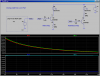
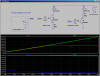
You can easily verify what i have stated above by doing a simple simulation.
 
Last edited:
Hi,


Well no, i meant that you have two choices here:
1. Regulate the LED current
2. Dont regulate the LED current

If you regulate then you do it one way (emtter resistor) but if you dont regulate then you do it another way (collector resistor, and estimate the current).

Hi again MrAl,
And thank you very much.

You mean regulating the LED's current by adjusting the Duty Cycle of the Port's output?

I wouldn't be able to do so, if that was what you meant, was it?

I must say that the Port's output is 3.3V, while VCC is 5V.
 
Hi again MrAl,
And thank you very much.

You mean regulating the LED's current by adjusting the Duty Cycle of the Port's output?

I wouldn't be able to do so, if that was what you meant, was it?

I must say that the Port's output is 3.3V, while VCC is 5V.


Hi,

Yes, regulating by changing the duty cycle of the port pin.
What can you not do this?
Why is the output only 3.3v with a Vcc of 5v ?
 
The VCC is not the voltage which operates the Uc, therefore they're different.

Whats wrong with estimating beta of at least 50, and calculate RB based on beta=50?
 
Whats wrong with estimating beta of at least 50, and calculate RB based on beta=50?
Then the transistor probably will not saturate. Beta is not used in calculations for a saturated switching transistor.
Beta is used in calculations for a linear transistor amplifier that has plenty of collector to emitter voltage and is never saturated.

For this constant current sink circuit, a series base resistor is not needed. The base voltage, not its current, sets the constant current in the LED.

The BJT is not supposed to saturate, but to be in its linear region.

if you don't use a base resistor, then:
V(Emitter) = 3.3V - 0.7V = 2.6V
V(Collector) >= 2.6V
V(LED) <= 2.4V

2.4V might not be enough for the LED to turn on.
Therefore you must have a base resistor in order to decrease V(Emitter) and by that increase V(LED).
 
Last edited:
This circuit is supposed to be a constant current sink.
Its base voltage is too high and its emitter resistor value is also too high so it will not work properly.
 
I realise this thread is an excellent lesson in transistor theory, and electronic calculations, but....seeing as its only a basic LED driver, used to light an LED from a low voltage, low power I/O,..... why not just use what parts/values you have available to you and judge the brightness of the LED?

With all the specific's,sure you can 'tweak' it, but how do you know that the LED won't be bright enough running at say...7mA? I don't think I have never put much thought into transistor LED drivers for 'standard' LED's (power LED's are obviously a bit different, as they require much more current). Just pick an NPN you have to hand, start with a reasonable series resistor for the LED, and start with a say a 10k base resistor. If you're really interested in whats going on, get your multimeter out, and start measuring voltages :D
 
Last edited:
This circuit is supposed to be a constant current sink.
Its base voltage is too high and its emitter resistor value is also too high so it will not work properly.

Given the base voltage (3.3V), why not using a base resistor to decrease the emitter voltage?

without a base resistor, the emitter resistor's voltage drop will always be 3.3V - 0.7V, no matter what its value is
 
This circuit is supposed to be a constant current sink.
Its base voltage is too high and its emitter resistor value is also too high so it will not work properly.

Not quite: I put the base resistor there on purpose. Look at the simulation below. Note that in my circuit, the transistor is not acting as a conventional emitter follower because its emitter voltage is much lower than it would be if it were not for the voltage drop across the LED.

The simulation shows a comparison of the LED current vs RE (the current determining resistor). Note that both circuits put essentially the same current I(D1) and I(D2) through the LEDs for 40Ω ≤ RE ≤ 200Ω.

Now look at the current through R2 and R4; note that AudioGuru's way loads the PIC Port a factor of 10 times higher than Mike's Way. For what benefit????

To see Mike's circuit act as a constant current sink for RE=80Ω (which makes the LED current 16mA), we would have to increase the supply voltage above 6V. The second sim shows the LED current as the LED supply sweeps from 4V to 8V. Note that above 6V, Mike's circuit keeps the LED current constant. Also notice that if the LED supply is operated at 6V or higher, you could leave out the base resistor, R4. If the circuit is going to be operated at less than 6V, then the base resistor is required.
 

Attachments

  • DF47.png
    DF47.png
    44.4 KB · Views: 168
  • DF47a.png
    DF47a.png
    43.8 KB · Views: 157
Last edited:
Status
Not open for further replies.

New Articles From Microcontroller Tips

Back
Top