Continue to Site

Welcome to our site!

Electro Tech is an online community (with over 170,000 members) who enjoy talking about and building electronic circuits, projects and gadgets. To participate you need to register. Registration is free. Click here to register now.

  • Welcome to our site! Electro Tech is an online community (with over 170,000 members) who enjoy talking about and building electronic circuits, projects and gadgets. To participate you need to register. Registration is free. Click here to register now.

Plasma cut 50

Status
Not open for further replies.
I use this video I don't have a powe supply to test but I use a phone charger that haves 9v output 350mA
In the pictures I'm showing the reading I get from the power adapter that is 13.50 and in the other picture is the reading touching the zener diode

To measure the zener diode and I'm getting a reading of 0.10 on the multimeter don't know if I'm doing it the right way please any help will be great, thanks !
 

Attachments

  • IMG_6632.JPG
    IMG_6632.JPG
    1.2 MB · Views: 203
  • IMG_6633.JPG
    IMG_6633.JPG
    1.2 MB · Views: 198
  • IMG_6634.JPG
    IMG_6634.JPG
    978 KB · Views: 206
I get abot 4 mm x 1.4 mm
Possibly this
MiniMelf (MMA), 0204 package
Metal Electrode, Leadless face
Who knows exactly how it's dimensioned

3.6 mm × 1.4 mm 0.25–0.4 W 200 V

Good catch on the band colors. Zener diodes will likely check regular diodes, but they are in-circuit.

Green - Schottky; Blue - Zener
i dint find it serch all ove the web but i found this part number or name dont know how to serch for this type of electronics,
SOD 80C LL34 MINI MELF
(MiniMelf (MMA) Size 0204: length: 3.6 mm, diam.: :1.4 mm. Typical rating for resistors = 0.25 to 0.4 watt / 200 V)
this have similar characteristics , will this work to replace the one im looking for ??? thanks !
 

Attachments

  • 31001317-0021697812ff4429b7215aa071307e5f.gif
    31001317-0021697812ff4429b7215aa071307e5f.gif
    24.4 KB · Views: 343
:banghead:I just notice something :banghead:when measuring:banghead: that is not the part I need This is the picture of the parts from the 2 ones that was not burn so sorry for not looking carfuly
 

Attachments

  • IMG_6644.PNG
    IMG_6644.PNG
    1.4 MB · Views: 260
Ok wait I'm stupid, I think I remove the black strip will trying to remove the glue, I just don't know what the hell im doing
 

Attachments

  • IMG_6648.PNG
    IMG_6648.PNG
    1.2 MB · Views: 202
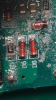
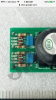
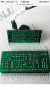
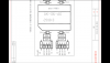
The circuit you have is very like;y to have similar bits nearby and for the Blank thing a resistor because of it's designation of R. A resistor marked 101 is 100 ohms. A "10" and 1 zero. so 221 is 220 ohms, 103 is 10K. Wattage you have to get by size,

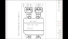
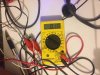
When you measure "in-circuit", the parts around the part your measuring interact, so when using the diode test and you get 000 and 000 in both directions, you need to know if it's a surrounding part.

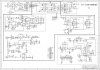
You may have to "reverse engineer". make a schematic from the PCB to enable better gueses.

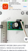
Zener diodes, the ones with the (based in your pdf) colored band will likeley act like regular diodes unless they are something like 2.1V.

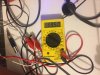
Your meter in the diode range may measure in mV rather than volts, so 686 is 0.686.

I have a $7.00 meter I got free that does this.

The value of a resistor that you can;t read, you may be able to make out parts of them and there may be a similar bit elesewhere on the board.

if you happen to find a bad zener diode that test bad in and out of circuit, your going to have to find a voltage source and a resistor to say limit the current to 1-10 mA and measure the voltage across it. For a 5.1 V zener diode, you;ll have ~0.6 one way and 5.1 the other.

A 9V battery and two 9V batteries in series would be a place to start.

Don;t forget to take photos before and after to check polarity.

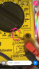
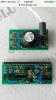
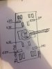
For the dimensions, I have a dial caliper, so i blew up your jpg with the ruler. Measured the ruler for 1 cm for my screen in mm. Now i have a conversion to apply for other components measured on the screen.


So, if I wanted to measure the black resistor, I could measure the screen value of the diode and I know the real dimensions, so i can calibrate that way.
 
Thanks that, will try and do all that, when you say "made a schematic of the pub board " is it something like the picture
 

Attachments

  • IMG_6669.JPG
    IMG_6669.JPG
    155.4 KB · Views: 856
Ok before I star drawing the schematic I was looking to know the name of the particular part and I found a lot of similar ones in one of the pictures you can actually see the value of the parts Can I use one of this parts for replacement ? Mine is a plasma cut50 and not a welder, that I think this board at made for , again thanks for all the help!
 

Attachments

  • IMG_6673.PNG
    IMG_6673.PNG
    697.7 KB · Views: 259
  • IMG_6674.PNG
    IMG_6674.PNG
    394.7 KB · Views: 253
  • IMG_6675.PNG
    IMG_6675.PNG
    551.8 KB · Views: 235
  • IMG_6680.PNG
    IMG_6680.PNG
    1.2 MB · Views: 258
  • IMG_6681.PNG
    IMG_6681.PNG
    1.2 MB · Views: 241
  • IMG_6683.PNG
    IMG_6683.PNG
    1.1 MB · Views: 215
  • IMG_6685.PNG
    IMG_6685.PNG
    740.5 KB · Views: 213
Last edited:
I'm looking to see if I found a electric diagram schematic cause I know I cannot do the reverse engineering your mentioning I only know the basics of soldering and tutorial I found on YouTube but only basic stuff, here I found a interesting page https://www.emil.matei.ro/
 
This are some reading I did to the part don't know if I can replace using parts showing in the video of the schematic?
 

Attachments

  • IMG_6867.JPG
    IMG_6867.JPG
    795.7 KB · Views: 219
  • IMG_6844.PNG
    IMG_6844.PNG
    150.2 KB · Views: 223
  • IMG_6845.PNG
    IMG_6845.PNG
    157.8 KB · Views: 220
Status
Not open for further replies.

Latest threads

New Articles From Microcontroller Tips

Back
Top