Continue to Site

Welcome to our site!

Electro Tech is an online community (with over 170,000 members) who enjoy talking about and building electronic circuits, projects and gadgets. To participate you need to register. Registration is free. Click here to register now.

  • Welcome to our site! Electro Tech is an online community (with over 170,000 members) who enjoy talking about and building electronic circuits, projects and gadgets. To participate you need to register. Registration is free. Click here to register now.

Plasma cut 50

Status
Not open for further replies.

agguilar

New Member
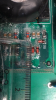
Hi all I'm looking to fix my machine I'm in this forum because here are all the experts in this field, I don't know much I have fix other electronics but this is my first machine whit hi voltage parts and I will like to be safe first before star the fix
 

Attachments

  • IMG_6564.PNG
    IMG_6564.PNG
    1.3 MB · Views: 303
  • IMG_6565.PNG
    IMG_6565.PNG
    1.4 MB · Views: 271
Without a schematic, it will likely be tough.

The high voltage aspects would be mains voltage. If they rectify it, it gives you about 400 Vdc. The second is the ignition circuit.

here https://www.google.com/search?q=lin...kKHd7HA1cQ9QEwAHoECAAQBA#imgrc=hcCyZYWRWlfpYM: is a block diagraam of an SMPS.

The "commons" of the primary cause some very difficult issues with trouble shooting. Don;t probe the primary relative to ground. i.e. with a grounded scope or meter.

Make sure your leads are up to the insulation voltage.

With high voltage, an arc can jump.

Generally, you make probing connections with the power off.

There is always the "one hand in the pocket rule"

The charge on the ignition circuit is usually short-lived.

You do need to discharge HV circuits before working on them. Capacitors on HV circuits CAN sometimes build up a charge AFTER they have been discharged. These are usually large capacitors. They need to be stored with a "keeper" or a short between the terminals.

HV diodes have a very large voltage drop. Possibly 9 or 10 Volts, so the diode test in your meter is worthless. You can still test with a resistor and battery and measure the voltage across the diode.

One system I routinely worked on had a key to open the HV cover. That power supply was capable of 1bout 15 kV at 1.5 Amps. It could obviously do some serious damage. I had an insulated discharge stick. https://www.tomwblack.com/phenix/40400_Discharge_Ground_Sticks.pdf Your not likely to need one of these, but I did and it was much shorter/

Other systems I worked on (100 kV at 0.1 A) X-ray generator and a lamp that required a 40 kV start pulse. Then there were CRT based TV's.

Most important:
1) One hand in the pocket.
2) Make connections with the supply off.
3) Safely discharge the system.
4) Voltages across some capacitors can return after being discharged.
5) Don't work alone. I did that lots of times.
6) Don't work under the influence or when tired.
7) Safety glasses

The dielectric strength of air is 30 kV/cm. Also see https://en.wikipedia.org/wiki/Dielectric_strength

High current is a separate issue. Another useful article is: https://en.wikipedia.org/wiki/Arc_flash
A car battery with a wrench across the terminals is a big problem.

This https://www.repairfaq.org/sam/safety.htm is a bit more comprehensive.
 
I will like to order the parts but really don't know the specific par number or any info other than the pictures
 

Attachments

  • IMG_6561.PNG
    IMG_6561.PNG
    1.3 MB · Views: 290
  • IMG_6593.jpg
    IMG_6593.jpg
    70.8 KB · Views: 292
  • IMG_6595.PNG
    IMG_6595.PNG
    1.2 MB · Views: 286
the K2837 is really a 2sk2837

https://www.rdd-tech.com/sites/default/files/attachment/2SK2837_datasheet_en_20090929.pdf

The glass diodes could be anything from a fast recovery rectifier, to a standard diode, to a TVS diode, a shotkey or a zener diode.

Looking for "markings" on the part will help. They won;t necessarily be a part number. Reverse engineering that portion of the circuit can give the experienced a clue.

Small valued resistors in the general area also have a tendency to change value.

If the MOSFETS are in parallel it sometimes makes a lot of sense to match them in terms of Vth and admittance. Say 20%. Admittance of 10-17 is 70%. 2 to 4 is 200%.

I like Silpads for a thermal mounting kit. Kits also include a bellville (dome shaped) washer that exerts nearly constant force on the tab. These pads don;t need the silicone grease.
 
In this video it shows a similar board and it's fixing similar part just that the one in my board is another color code and different position this is the YouTube video and the picture of the explanation of the part that he is fixing hope it helps to identify my part, thanks
 

Attachments

  • IMG_6600.PNG
    IMG_6600.PNG
    1.4 MB · Views: 205
I have found a video that shows how to test a diode but will need some parts mention like power supply etc.
 
Many multimeter have a diode scale. They measure the voltage drop across a diode junction up to about 3 Volts.
A Zener diode will basically look like a regular diode because the breakdown voltage is controlled. Breakdown (peak reverse voltage) is non-destructive if current limited.

Schottky diodes have a low forward voltage drop around 0.2 V. Silicon diodes around 0.6. Diodes normally short when they fail. High voltage diodes (think microwave) have a much higher drop. Fast recovery diodes are used when the switching frequency is high. TVS diodes absorb surges and have a large body.

You don't see very many tunnel diodes anymore nor Germanium diodes.
 
I had a Plasma cutter very similar that did not work. When I scraped it the fault was a thermal fuse on the heat sink had gone open circuit.
 
My plasma cutter the problem is aparthy visible burn parts from previous owner not cleaning the tip of the machine toching the metal whit the plasma tip and using same electric braker for compresor, and I will like to fix it I just don't know the part number to buy I already order the 2sk2837 Power MOSFET (in picture) and I just need to find out the value of the switching diode mini- MELF (in picture I already remove the 2 burn ones) so I can serch online electric stores and hopefully buy them to test the machine
 

Attachments

  • IMG_6608.PNG
    IMG_6608.PNG
    117.5 KB · Views: 224
  • IMG_6593.jpg
    IMG_6593.jpg
    70.8 KB · Views: 208
IF an ES3j https://www.mouser.com/datasheet/2/308/ES3J-1296689.pdf will fit, you can try it. Mouser has them.

The MOSFET has a lead spacing of 5.46 mm. A standard DIP 0.1" or 2.54 mm.

You just need to take a picture with something of a known size in it, in about the same plane as the part and measure th distance photographically on your screen. If I needed a small reference a piece of wire could would. i.e. 22 AWG

You could even use a dime if you had to.
wikipedia said:
being .705 inches (17.91 mm) in diameter and .053 inches (1.35 mm) in thickness.

This https://www.modularcircuits.com/blog/articles/h-bridge-secrets/h-bridges-the-basics/ should be useful too.
 
Last edited:
Thanks great info! Here are the picture I use cm, plus I found a good video of a similar machine and the persons explain more in detail the parts here is the link ( from minute 10 to 26 )
 

Attachments

  • IMG_6611.PNG
    IMG_6611.PNG
    1.6 MB · Views: 233
  • IMG_6612.PNG
    IMG_6612.PNG
    1.5 MB · Views: 219
Hopefully, later tonight I can get good measurements. The ruler is probably close enough, The first step is getting dimensions and then the package type or to see if another package fits.

Here https://en.wikipedia.org/wiki/Surface-mount_technology as you can see there are typical diode packages as well as SMT package types.

The one caution is that there are TWO systems for chip resistors and the like and they don't differentiate them.
A 1206 package can easily be handled. Just the numbers are usually used.

3216 1206 3.2 mm × 1.6 mm 0.125 in × 0.06 in 0.25[18]
 
I get abot 4 mm x 1.4 mm
Possibly this
MiniMelf (MMA), 0204 package
Metal Electrode, Leadless face
Who knows exactly how it's dimensioned

3.6 mm × 1.4 mm 0.25–0.4 W 200 V

Good catch on the band colors. Zener diodes will likely check regular diodes, but they are in-circuit.

Green - Schottky; Blue - Zener
 
Last edited:
Status
Not open for further replies.

Latest threads

New Articles From Microcontroller Tips

Back
Top