Continue to Site

Welcome to our site!

Electro Tech is an online community (with over 170,000 members) who enjoy talking about and building electronic circuits, projects and gadgets. To participate you need to register. Registration is free. Click here to register now.

  • Welcome to our site! Electro Tech is an online community (with over 170,000 members) who enjoy talking about and building electronic circuits, projects and gadgets. To participate you need to register. Registration is free. Click here to register now.

PicKit2

Status
Not open for further replies.

nomdomokunnom

New Member
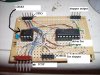
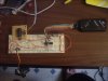
Hi, I recently purchased the pickit2 debug express (PicKit2 + 44-pin demo board) from Farnell and started playing around with the included PIC, but I'd like to experiment with using PICs on a breadboard rather than just making the debug board's LEDs light up, etc., so I'd like a programmer which can be used with DIP-style PICs; is there a recommended device compatible with the PicKit2 which can be used to program these types of PICs, and can someone suggest where I can purchase it from? I don't want to buy from microchip because of various issues I found with that last time.

I believe this may be what I'm looking for, but could use an expert opinion before I buy it, as I have only just started using PICs.

Thanks in advance.
 
The PICKit2 already does that - you just need to make a little board with a socket on that plugs in the PICKit2, or use ISCP from the PICKit2 direct to the target board.

If you wanted you could buy a ready made board, but a little bit of veroboard, a socket, and a connector for the PICKit2 is all that's required, and simle to make.
 
All the better if I can simply make it myself, then; could you point me to a schematic I could use for this? As I said I have very little experience with PICs and related technologies, so I don't know what "ISCP" means or how to make the board. Thanks for the help.
 
I like to use boards like this
board-jpg.46228
 

Attachments

  • board.JPG
    board.JPG
    98.2 KB · Views: 958
Last edited:
All the better if I can simply make it myself, then; could you point me to a schematic I could use for this? As I said I have very little experience with PICs and related technologies, so I don't know what "ISCP" means or how to make the board. Thanks for the help.

Here take a look at this it for the junebug but it's the same for the pickit2 just the pickits only has where you hook up the ICSP

That's the low pin count board that came with the pickit2 it's a good little board to get started with
 
Last edited by a moderator:
One good answer is a programming board I found on ebay. It has ZIF sockets that will handle almost any DIP-packaged PIC:

**broken link removed**

**broken link removed**

But the better answer is to use ICSP - In Circuit Serial Programming. The PICkit 2 is connected to a couple pins of the PIC while it's in your circuit, and can even provide power to your circuit. When you change the code and need to download it, just click a button on the screen...or even the red button on the PICkit 2. Makes it fast and simple to try things out as you go.

Take a look at this **broken link removed** and other stuff at **broken link removed**.
 
Last edited:
Jon I think we said that
But the better answer is to use ICSP - In Circuit Serial Programming.
He has a pickit2 with a smp pic on it the 44 pin . He wanted to see ideas on how to use ICSP why didn't you show him this here a real
nice board that Jon makes **broken link removed**
 
Only one bad thing wrong with this is it uses a phone jack for ICSP or what is called a ICD I think that's right spelling.
**broken link removed**

You would be better off using a solder less bread board like this
like-this-jpg.46230
 

Attachments

  • like this.JPG
    like this.JPG
    62.8 KB · Views: 945
Hmm I think I'd better look into how the programming / ICSP works before I attempt this; right now AFAIK, the demo board I'm using with the PicKit2 is magical. I have no idea which pins do what or how the pickit2 programs them, which is why I'm eager to use the PICs in circuits and figure it all out. I guess i'd better read up on the theory first. Thanks for all the pictures and explanations guys, I'll be sure to have a good look into these when I'm a bit less clueless.

be80be said:
You would be better off using a solder less bread board like this

I was hoping that might be do-able, I was planning on trying that.
 
Last edited:
Here this should get you started. The sch is for a 16f628a but you can use the layout for any chip just read the data sheet page 4 on most show the pin out for your chip
 

Attachments

  • ICSP.PNG
    ICSP.PNG
    21.9 KB · Views: 2,198
  • pickit2.PNG
    pickit2.PNG
    21.5 KB · Views: 473
ICSP - In circuit serial programming.

What is it all about? It beats pulling out the chip back and forth to the programmer and to the breadboard/prototyping area, and you can program it directly *right* into the prototyping circuit.

Try to read the PICKit 2 manual - especially the descriptions about each pins inside. And also, don't forget to read the microcontroller datasheet to locate the programming pins. :D
 
Hi,

Nigel and the others have already came out with explanations of the ICSP and how to use it. Here is a document which shows you the connections of different PIC chips for ICSP:

https://www.electro-tech-online.com/custompdfs/2010/09/30277d.pdf

Otherwise if you want to go for a target board, than i have the schematic and board layout for one usable with 18F PICs(better version posted by Be80be provided/designed by Jon) in my blog.
 
Last edited:
The board posted by Be80be is actually my design. More information about it can be found here. It's offered at low cost.


Jon
I said it was your board if you read my post. I don't think there talking about your board there talking about my
schematic
icsp-png.46231


Here is Jon Chancler very nice board for some pic 28 pin chips you can find it here ThrowAwayPIC
 
He wanted to know about ICSP

1. how you hook up your pickit2
That's in the pdf that came with the pickit2 if you don't no where to find that here is mine https://www.electro-tech-online.com/attachments/pickit2-user-guide-51553e-pdf.46259/

2 . What kind of board to use

I would use a bread board **broken link removed**

You can bread board any pdip chip that microchip sells . And if you don't like something you can change it easy > premade boards you for the most part stuck
with what you get.
 

Attachments

  • PICkit2 User Guide 51553E.pdf
    2.1 MB · Views: 619
Thanks for all the info guys; I've bookmarked the thread and I'm planning on having a go at connecting it up as explained with a breadboard as soon as I get a DIP-style PIC (I gave someone the Maplin order code and got them to pick one up for me, but Maplin somehow managed to palm them off with a low-power, low-frequency transistor instead, while charging me the full price. I'm going to swap it out tomorrow and give this a try; I'm sure all the information I'll need is available in the many in-depth replies; thanks again guys.
 
Otherwise if you want to go for a target board, than i have the schematic and board layout for one usable with 18F PICs(better version posted by Be80be provided/designed by Jon) in my blog.

Be80be, sorry, you misunderstood my comment. Thank you for posting the TAP-28 board. I was actually replying to Wond3rboy's comment about having a better board design. "Better" is a relative term. The TAP-28 is an application board rather than a traditional dev board, and it works well for connecting to read-world stuff.
 
Status
Not open for further replies.

Latest threads

Back
Top