Continue to Site

Welcome to our site!

Electro Tech is an online community (with over 170,000 members) who enjoy talking about and building electronic circuits, projects and gadgets. To participate you need to register. Registration is free. Click here to register now.

  • Welcome to our site! Electro Tech is an online community (with over 170,000 members) who enjoy talking about and building electronic circuits, projects and gadgets. To participate you need to register. Registration is free. Click here to register now.

picbasic program not working as expected

Status
Not open for further replies.

bigal_scorpio

Active Member
Hi to all,

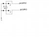
I have just written a simple program to control 2 separate latching relays, the kind with just a single coil that needs a reverse voltage to switch over.

All I wanted was for the pic to detect a button pressed, either on GP4 or GP3 then if it was GP3 it would pulse GP1 high and GP2 low for a second, then store the state of B1 so another press of GP3 would change its state and so on, the same applies for GP4 controlling the pulse to relay 2 from GP0 and GP5.

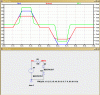
The program compiles ok and burns but on my test board the only lights ever to pulse are on GP0 and GP1! GP2 and GP5 are never lit which I would expect to work on every other press.

What am I missing here? Also on powering the circuit GP0, 1, 2 and 5 are all lit permanantly until a switch is pressed, then its back to how I described earlier.

I am puzzled although this is the usual feeling after a Friday night out;)

Anyone see whats wrong with the code please?

Al
Code:
'*  Name    : latching relay1.BAS                                      *
'*  Author  : [select VIEW...EDITOR OPTIONS]                    *
'*  Notice  : Copyright (c) 2011 [select VIEW...EDITOR OPTIONS] *
'*          : All Rights Reserved                               *
'*  Date    : 18/06/2011                                        *
'*  Version : 1.0                                               *
'*  Notes   :  12F629 latching relay controller for latching 
'*          : relays with single coil                                                  *
'*          :                                                   *
'****************************************************************
Include "ALLDIGITAL.PBP"
TRISIO = %011000
B1 var byte
B2 var byte

MAIN:

If GPIO.3 = 0 then gosub sw1 'get switch input
if GPIO.4 = 0 then gosub sw2 'get switch input

Goto MAIN

sw1:
READ 0,B1   'read stored value from eeprom
B1 = NOT B1  'change B1 value
WRite 0,B1   'write new value to eeprom

If B1 = 0 then  'send pulse to relay
GPIO.1 = 1
GPIO.2 = 0
pause 1000
GPIO.1 = 0      'stop pulse
ENdif
IF B1 = 1 then   'send opposite pulse to relay
GPIO.1 = 0
GPIO.2 = 1
pause 1000
GPIO.2 = 0      'stop pulse
endif
return


sw2:
READ 1,B2
B2 = NOT B2
WRite 1,B2

If B2 = 0 then
GPIO.0 = 1
GPIO.5 = 0
pause 1000
GPIO.0 = 0      'stop pulse
endif
IF B2 = 1 then
GPIO.0 = 0
GPIO.5 = 1
pause 1000
GPIO.5 = 0      'stop pulse
endif
return
end
 
Cheers Ian,

That did the trick mate, but I've just thought of another problem!

How do you put a clamping diode on a coil that needs to be bi-directional? Doh!

Al
 
Cheers Ian,

That did the trick mate, but I've just thought of another problem!

How do you put a clamping diode on a coil that needs to be bi-directional? Doh!

Al

hi Al,
Lousy weather.

You could use two zener diodes in opposing series, whats working voltage.?
 
Hi Eric,

Fine up here mate - so far.

As to the voltage it will be 5v although the actual relays coils are rated 3v I only intend to give a very short pulse as I was hoping to drive the relays directly from the pics pins. The current is max 30mA needed to pull in.

Can you expand on the zener idea as I have never used them for clamping in such a way.

Thanks Al
 
Just on a side note if B1 or B2 is pressed then you write the eeprom EVERY cycle.. This way the eeprom locations won't last two weeks...

Hi Ian,

How would you do it? I need to store the locations before power down obviously but I can't see any other way of keeping track of them. BTW the buttons will only get a few uses a week.

Al
 
Timer

OnEvent eeprom write

Event you could set timer to run in back ground 1 2 5 min. or hours
 
I had to use an external Fram (ramtron) over a billion write cycles.. If your project needed a RTC the DS1307 comes with 56 bytes of Sram.

There isn't many ways to do this... But if you say once or twice a week you should be ok .. internal eeprom has 100,000 write cycles
 
Hi Burt,

You have me baffled mate.

Let me explain the use I will be putting it to.

I have some momentary push switches in the car dash, they control things I have added over time, like an LCD clock etc.

I would have used latching switches for some things like switching the car hifi on and off but there were none available in the same style so when I built the switches in I could only use momentary, great for setting the clock but not so good for power switches where even using relays I would have had to have them permanantly energised.

I came across some latching relays that once activated to change over need no hold on current at all and these seemed ideal, but needed pos and neg swapping each time. So I wrote the program to do that and only need 1 switch per relay which is ideal but since most of the systems in the car are ignition dependent I need to power the pic from that and then when ign is off there is no power drain at all.

I didn't see a problem with the amount of eeprom writes as the switches will get little use, a few a week at the most, so do I need to worry about that in the current configuration?

Like I said earlier I am now trying to work out a way of snubbing the relays but am only used to doing that on normal polarised relays. I'm hoping Eric can shed some light on it.

Anyway any thoughts welcome so keep up the suggestions.

Thanks Al
 
I see now maybe this would work for you better there two wires that go to radio one is on when the car is running one is on even when the car is off

Let the one that's on when the car is off power the pic

Let the one that's on when the car is running tell the pic when to wake up and when to sleep

Then you could use the timer and OnEvent eeprom write to write when you want it to.
 
Last edited:
hi Al,
Whats the resistance of the 3V relay coils
 
Good morning Eric,

The resistance is 32 ohms.

BTW Still fine here! must be a rotherham record (unintentional pun) hehehe

Al
 
hi Al,
Thats approx 90mA.! the PIC is specified as approx 25mA max

EDIT:
A test edit.
 
Last edited:
hi Al,
You require a transistor driver between the PIC and the Relay
 
Hi Eric,

Yes I know its a bit high but on 5v with a very short pulse I am willing to risk it. Its the diode protection I can't figure out.

Looking on the net I seem to only get the ones for protecting with either dc or mains ac.

Any ideas mate?

Al
 
Last edited:
hi Al,
You require a transistor driver between the PIC and the Relay

Hi Eric,

I had hoped to do this without what would end up being just about an H-Bridge. If I had any of the motor driver ICs I would maybe have gone down a route using those, but its one of the things I have never had.

Do you think its worth a try with just the pic, I have a few of them and if one got fried I wouldn't be too upset. If I could just get the snubbers right.

Al
 
hi Al,
Choose zener diodes just above the working voltage of the PIC.

Look at this image.

Edit:
Testing
 

Attachments

  • AAesp01.gif
    AAesp01.gif
    26.6 KB · Views: 169
Last edited:
Will this work?

Hi guys,

Just wondered if this way of snubbing would work for the relay?

If I substituted the relay for the motor in the diagram below.

I must admit I still don't understand the Zener method you drew Eric and won't there be loss due to both the diodes and the resistor?

Anyway have a look at this and advise please.

Al
 

Attachments

  • snubbber.JPG
    snubbber.JPG
    9 KB · Views: 143
Status
Not open for further replies.

Latest threads

Back
Top