AtomSoft
Well-Known Member
Hey guys im trying to learn this VGA Stuff but no luck. Here is my code. Can someone test it on a CRT? I have a Samsung 19in (FLAT) but not working so im not sure why tho. It looks almost perfect... Here is my code.
Im trying to use RED only and the resolution is 640*480 @ 60hz. I think my monitor doesnt support this??? is that possible?
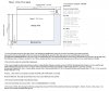
The schematic is SIMPLE..
VGA Cable PINS USED:
1 = RED = TIE THIS TO VCC
2 = BLUE = TIE THIS TO VSS
3 = GREEN = TIE THIS TO VSS
10 = GND = TIE THIS TO VSS
13 = HSYNC = RB0
14 = VSYNC = RB1
Im trying to use RED only and the resolution is 640*480 @ 60hz. I think my monitor doesnt support this??? is that possible?
The schematic is SIMPLE..
VGA Cable PINS USED:
1 = RED = TIE THIS TO VCC
2 = BLUE = TIE THIS TO VSS
3 = GREEN = TIE THIS TO VSS
10 = GND = TIE THIS TO VSS
13 = HSYNC = RB0
14 = VSYNC = RB1
Code:
/* *****************************************************************************
; *
; Filename: *
; Date: *
; File Version: 001 *
; *
; Author: Jason Lopez *
; Company: AtomSoft *
; *
;***************************************************************************** */
#include <p18f4620.h>
#include <delays.h>
#pragma config WDT = OFF, LVP = OFF, OSC = INTIO67, XINST = OFF
/************************************
Prototypes
*************************************/
void main(void);
//#define RED LATBbits.LATB0
//#define GREEN LATBbits.LATB1
//#define BLUE LATBbits.LATB2
#define HSYNC LATBbits.LATB0
#define VSYNC LATBbits.LATB1
/************************************
Main
*************************************/
void main(void){
int x = 0x0000;
OSCCON = 0x72; //8MHz clock
while(!OSCCONbits.IOFS); //wait for osc stable
ADCON1 = 0x0F; //Digital Pins (we dont need ADC)
TRISB = 0x00; //All Outputs
LATB = 0x00; //All Low
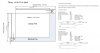
//H Refresh Rate: 37.861 khz aka 26.412 uS aka 52/53 Cycles
//V Refresh Rate: 72.809 hz aka 13.734 mS aka 27468 Cycles
HSYNC = 9;
VSYNC = 1;
while(1){
// RED = 1; //TIED HIGH and Green and Blue are tied LOW
for(x=0;x<480;x++){
Delay10TCYx(2);
Nop();
Nop();
Nop();
Nop();
Nop();
Nop();
Nop();
Nop();
Nop();
Nop();
Nop();
Nop();
Nop(); //25 us including FOR LOOP
//SYNC FROM HERE
Nop();
Nop(); //1us
HSYNC = 0;
Nop();
Nop();
Nop();
Nop();
Nop();
Nop();
HSYNC = 1; //4us
Nop();
Nop();
Nop(); //1.5us
//SYNC DONE took 6.5us + 25us data = 31.5us Horizontal Timing
}//15.12ms loop
Delay10TCYx(70); //350us before vertical sync
VSYNC = 0; //Sync ready
Delay10TCYx(11);
Nop();
Nop();
Nop();
Nop();
Nop();
Nop();
Nop();
Nop();
Nop();
VSYNC = 1; //60us Sync hold
Delay10TCYx(203); //1.015ms end
//Vertical Sync done! took 1.425ms
//Total 480 Lines loop * 31.5us per line + 1.425ms =
// 15.12ms + 1.425ms = 16.545ms total === 60.44 hz refresh rate...
}
}")
 16F88 will be fine.