Hi guys, what are the minimum circuit required to start the circuits? What are the Pins that we can ignore?
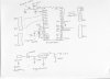
I had patched the circuit as given in PICDEM 2 Plus schematics but it is not working. Then I used a breadboard to patch the circuit And it is not working as well.
I had only patched the followings:
Pin 1 to MCLR
Pin 11 to +5V
Pin 12 to GND
Pin 13 to Oscillator
Pin 14 to Oscillator
Pin 31 to GND
Pin 32 to +5V
the programming is as followed:
#include <p18f4520.h>
#include <delays.h>
void main(){
int i;
ADCON1=0x0F;
PORTB=0x00;
TRISC=0x00;
TRISB=0x00;
while(1) {
Delay10KTCYx(15);
LATB=0x00;
Delay10KTCYx(150);
LATB=0b11111111;
LATC=0b00001001;
}
I programmed the PIC using PICDEMO 2 Plus, then remove the RJ-11 cable and the LED (PORT B 0-3)lit up, hence software shld be working.
When I remove the Chip and put in the circuit I made, there is not voltage at Port B.
I had measure the followings:
Pin 1 supposed to be 5V and GND when "reset" is switch pressed, and it work well
Pin 11 supposed to be 5V, I measured 5V
Pin 12 supposed to be GND, I measured GND
Pin 31 supposed to be GND, I measured GND
Pin 32 supposed to be 5V, I measured 5V
Pin 34-40 supposed to be alternating between 5V and GND, NO VOLTAGE IS DETECTED
Hence I had concluded that the microchip is not working or "switch on". Is there any thing I miss out in the hardware circuit that I have to include? or would it be some other reasons why the circuit is not working
Pls help, Thanks