lloydi12345
Member
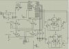
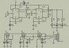
I have two PCBs. PCB1 contains PIC, Comparator and hbridge. PCB2 contains the IR LEDs and IR receiver modules. The first sensor is located at front, 2nd at left side of the mobile car and 3rd at the right side. I would like first to try it on flashing LEDs on the PIC before giving it a try on the motors. When an obstacle is detected in front, the 2nd LED will light. If an obstacle is detected on left, the 1st LED will light. If an obstacle is detected on right, the 3rd LED will light. I am having problems in using in the sensor part. The 1st sensor doesn't make the 2nd LED light even if I place an obstacle. Left sensor and right sensor works very well without any problems. The 3 IR receiver modules are different from each other that's why the schematic for each IR receiver module is different.
When I try PCB2 disconnecting from PCB1 and try PCB2 on a breadboard with only LM324 and variable resistor. The output of LM324 is connected to a visible LED to show that there is an obstacle detected. On if there's no obstacle and Off if there's an obstacle. The sensors are not having any problems at all. The 3 sensors function well. Is it possible to have problems with my program code?
Here's my source code:
Code:
	list		p=16f877A	; list directive to define processor
	#include	<p16f877A.inc>	; processor specific variable definitions

	__CONFIG _CP_OFF & _WDT_OFF & _BODEN_OFF & _PWRTE_ON & _XT_OSC & _WRT_OFF & _LVP_OFF & _CPD_OFF


CBLOCK 0x21
	FIRST
	SECOND
	THIRD
ENDC


	ORG     0x000
  	goto    main              ; go to beginning of program

	ORG     0x004
; isr code can go here


main

BANKSEL TRISC
MOVLW 0x00
MOVWF TRISC
MOVLW 0XFF                ;RB inputs (RB4-RB7 are the only port bits used as input)
MOVWF TRISB
BANKSEL PORTC

FORWARD:
	MOVLW B'00000001'
	MOVWF PORTC
	CALL DELAYY
	MOVLW B'00000010'
	MOVWF PORTC
	CALL DELAYY
	MOVLW B'00000100'
	MOVWF PORTC
	CALL DELAYY
	MOVLW B'00000101'
	MOVWF PORTC
	CALL DELAYY
	MOVLW B'00000110'
	MOVWF PORTC
	CALL DELAYY
	MOVLW B'00000111'
	MOVWF PORTC
	CALL DELAYY
	MOVLW B'00000000'
	MOVWF PORTC
	CALL DELAYY
	MOVLW B'00000111'
	MOVWF PORTC
	CALL DELAYY

MOVE:
	BTFSS PORTB, 4
	GOTO SENSOR0
	GOTO SENSOR1

SENSOR0:
	BTFSS PORTB, 5
	GOTO SENSOR00
	GOTO SENSOR01

SENSOR00:
	BTFSS PORTB, 6
	GOTO SENSOR000
	GOTO SENSOR001

SENSOR01:
	BTFSS PORTB, 6
	GOTO SENSOR010
	GOTO SENSOR011

SENSOR1:
	BTFSS PORTB, 5
	GOTO SENSOR10
	GOTO SENSOR11

SENSOR10:
	BTFSS PORTB, 6
	GOTO SENSOR100
	GOTO SENSOR101

SENSOR11:
	BTFSS PORTB, 6
	GOTO SENSOR110
	GOTO SENSOR111

SENSOR000:
	MOVLW B'00000111'
	MOVWF PORTC
	CALL DELAYY
	GOTO MOVE

SENSOR001:
	MOVLW B'00000011'
	MOVWF PORTC
	CALL DELAYY
	GOTO MOVE

SENSOR010:
	MOVLW B'00000110'
	MOVWF PORTC
	CALL DELAYY
	GOTO MOVE

SENSOR011:
	MOVLW B'00000010'
	MOVWF PORTC
	CALL DELAYY
	GOTO MOVE

SENSOR100:
	MOVLW B'00000101'
	MOVWF PORTC
	CALL DELAYY
	GOTO MOVE

SENSOR101:
	MOVLW B'00000001'
	MOVWF PORTC
	CALL DELAYY
	GOTO MOVE

SENSOR110:
	MOVLW B'00000100'
	MOVWF PORTC
	CALL DELAYY
	GOTO MOVE

SENSOR111:
	MOVLW B'00000000'
	MOVWF PORTC
	CALL DELAYY
	GOTO MOVE


DELAY:						;	1 second delay
		MOVLW .2
		MOVWF THIRD
LOOP_1_SEC:
		MOVLW .250
		MOVWF SECOND
LOOP_125_MS:
		MOVLW .250
		MOVWF FIRST
LOOP_.5_MS:
		NOP
		DECFSZ	FIRST,F
		GOTO	LOOP_.5_MS

		DECFSZ 	SECOND,F
		GOTO	LOOP_125_MS

		DECFSZ	THIRD,F
		GOTO	LOOP_1_SEC
		return

DELAYY:

		MOVLW .2
		MOVWF THIRD
LOOP_1_SECC:
		MOVLW .200
		MOVWF SECOND
LOOP_125_MSS:
		MOVLW .200
		MOVWF FIRST
LOOP_.5_MSS:
		NOP
		DECFSZ	FIRST,F
		GOTO	LOOP_.5_MSS

		DECFSZ 	SECOND,F
		GOTO	LOOP_125_MSS

		DECFSZ	THIRD,F
		GOTO	LOOP_1_SECC
		return


END
Attachments
Last edited:
