Continue to Site

Welcome to our site!

Electro Tech is an online community (with over 170,000 members) who enjoy talking about and building electronic circuits, projects and gadgets. To participate you need to register. Registration is free. Click here to register now.

  • Welcome to our site! Electro Tech is an online community (with over 170,000 members) who enjoy talking about and building electronic circuits, projects and gadgets. To participate you need to register. Registration is free. Click here to register now.

PIC16F84A + 4017 Decade Counter + audio question

Status
Not open for further replies.

Peter_wadley

New Member
Hi,

Quick Query:

The PIC16f84A has 5A + 8B = 13I/O pins, as if you all didnt know :p

Question:

If I were to connect a 4017 cmos decade counter to each output.. 13 (unless there are some pins which cant output.. yeah still havent understood which ones!!!)

Would I be able to control 13 x 10 = 130 LEDs individually!!!!!!!!!!!!????????

Would transistor be needed to increase brightness?

Thanks,
Peter Wadley
 
With demultiplexers, 13 bits will get you 8191 individual outputs. Flip flops can toggle each one on or off.
 
You'll want to mux the LEDs. One easy way would be be a transistor driver (you could use the 4017 with a UL2803 driver) to run 8 columns and a PIC 16F877 (lots of I/O) to drive the rows directly.

8x24 (total of 26 I/O pins) is 192 LEDs and that still leaves some I/O too. Also much less current than driving directly.

Toronto eh. Have you visited Creatron Inc on College? I'll be there this Thursday evening.

PS stop using the 16F84, there shoud be a campain...
 
Last edited:
The 4017 will only allow one LED to be on at a time per 4017.

If you want to be able to control the LEDs individually, use a Shift Register such as the 74HC164. It is an 8 bit serial in, parallel out SR. Note that you will need a common clock line (or a common data line) and individual data lines (or clock lines).

However, the advantage of the 74HC series is that it has 25 mA current source/sink capability which is adequate to drive ordinary LEDs.
 
ljcox said:
The 4017 will only allow one LED to be on at a time per 4017.

If you want to be able to control the LEDs individually, use a Shift Register such as the 74HC164. It is an 8 bit serial in, parallel out SR. Note that you will need a common clock line (or a common data line) and individual data lines (or clock lines).

However, the advantage of the 74HC series is that it has 25 mA current source/sink capability which is adequate to drive ordinary LEDs.
Are you suggesting using one 74HC164 (or 74HC595, etc.) SR for each set of 8 LEDs (100% duty cycle for each LED)?

I'm not sure a '164 would be a good choice because it doesn't use a 'latch' or 'strobe' control to transfer the contents of the shift register to the outputs. Any data shifted in will immediately show up on the outputs and this might make the display a little wierd during updates.
 
Last edited:
Your idea will work fine. I found one circuit that uses a 74LS193, 4 bit counter feeding a 74LS154 demultiplexer that would give you 16 X 12 = 192. 74259 8 bit latches would be better than flip flops but forget that if you can keep updating the LEDs. You would need a bunch of them. I found another circuit that made a 10 X 10 LED scope using a 4017 counter and an LM3914N dot/bar display driver.
 
:mad: My long reply was not posted!!!

Here is a short version:

PIC16F877 = too expensive for LED sequency project..

Id like to do this with my one of my PIC16F84As..

Ok, I only need to be able to individually controller 50 LEDS.. therefore at any given time I will be able to have 50 LEDS on..

My thought process was this..

Since the 4017 can handle 10 LEDS.. use 5 of them on rb0-rb4

and since the 4017 change there state with a high pulse edge I could control each LED by quickly cycling to the one I would like..

hmm but then I would only able to have 10 on -- one per 4017 at a time..

Can someone explain how the shift register would work?

Im going out to the store soon and would really like a couple chips numbers..

From what ive read I need 4x 74154 demux chips (64LEDs)

But wouldnt I need 5 pins for each DEMUX 1 = input 4 = selectors.

I wouldnt have enough pins..

I guess this where shift registers comes in .. :| ?

Again..
50 individually controlled LEDs that can be lit simultaneously

thanks, please remember that I am a still a noob when it comes to TTL control.
 
Peter_wadley said:
Id like to do this with my one of my PIC16F84As..

Ok, I only need to be able to individually controller 50 LEDS.. therefore at any given time I will be able to have 50 LEDS on..

Dump the antique 16F84 and use a 16F628 instead (which is lots cheaper anyway), consult my tutorials and drive 64 LED's with no extra chips.
 
Nigel,

You must be getting SO incredibly sick of seeing people still trying to make projects using the 84a hehe

You might as well just put it in your signature :)

I know exactly what you mean though. I cant wait to use these 3 chips up! They are great for learning but soon turn very annoying!

I cant wait to start using the 16F628 and 16F877.. A/D convert.. mouth drools

But still is there anyone that can help me with the 74154 1-16 demux?

Thanks
 
I agree with the multiplexing suggestions. Not sure your '4017 is a good choice though.

Most multiplexing designs will power one column or row at a time while driving one or more of the LEDs in that column or row, respectively.

If we "scan" columns, duty cycle is inversely proportional to the number of columns (2 cols = 50% duty cycle, 4 cols = 25% duty cycle, 8 cols = 12.5% duty cycle, etc.). If an individual LED requires 10-ma current for full brightness at 100% duty cycle it's going to need 20-ma at 50% duty cycle, 40-ma at 25%, and 80-ma at 12.5% for full brightness. If you have an 8 x 8 matrix of multiplexed LEDs you'll have a 12.5% duty cycle and each column driver should be capable of supplying 640-ma when all 8 LEDs in that column are lighted. Each row driver needs to supply 80-ma for one LED at a time in each column.

Directly driving rows from PIC pins works well for one or two columns but the brightness starts to suffer as we add more columns. Use row drivers if you have more than a few columns and you need full brightness.

mux-ca-cc-png.12390

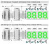
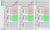
You can see we're using a lot of pins at this point so you might consider using a different driver IC with the common anode LED configuration. The Micrel MIC5821 or the pin-for-pin compatible Allegro A6821 is an 8-bit serial to parallel sinking driver with a 3 pin interface (Data, Clock, and Strobe). Here's a full brightness design that uses 9 I/O pins.

matrix-display-9-pin-7-seg-png.12392


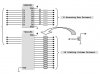
In this design PORTB is used as a column driver bus when the Strobe/OE pins are low (display on) and as a data bus to load the driver shift register when the Strobe/OE pins are high (display off). Simply blank the display at the beginning of each "scan" interrupt by taking Strobe/OE high, load new data into the SR, reset the PORTB column bus for the next column, and finally turn the display back on by taking Strobe/OE low. This only takes a few microseconds in the ISR.

You can also setup the PIC PWM module with a period equal to the column "scan" interval and drive the MIC5821 Strobe/OE pins directly from the PWM CCP1 pin output. You'll need a minimum PWM duty cycle of 5% or so to insure that you have time at the beginning of each interrupt cycle to load the SR while the display is off. Adjusting the PWM duty cycle from 5% to 100% will take the display from full brightness to black, respectively.

While these examples use 7-segment displays, I'm sure you realize you can use discrete LEDs or Bar/Graph LEDs or 8x8 matrix modules instead. And the "high performance" designs also scale up or down quite nicely.

matrix-8x8-10-png.12393
 

Attachments

  • Mux CA & CC.PNG
    Mux CA & CC.PNG
    43.6 KB · Views: 14,523
  • Matrix Display (9 pin 7-seg).PNG
    Matrix Display (9 pin 7-seg).PNG
    76.4 KB · Views: 10,901
  • Matrix 8x8 (10).PNG
    Matrix 8x8 (10).PNG
    133.1 KB · Views: 12,508
Last edited:
Peter,

I'm still not sure a '4017 or a '154 would be a good choice. Neither can be used to sink or source enough current to a multiplexed display without adding driver transistors and in the case of the '154 you really don't want to "scan" more than about 8 columns as the duty cycle is much too low and the pulse current requirements are way too high.

In all fairness I should mention that some of the direct drive low brightness designs might work well for your application too.

led_bar-dot_prototype-jpg.7001
 
Last edited:
Are you trying to do something like this to drive LED columns (common cathodes)?

matrix-driver-concept-2-jpg.12395

I would maybe use the 74HC4017 to drive transistors for 8 columns but I'm not sure I could recommend using the 74HC154 to drive transistors for 16 columns for the reasons stated earlier (too low a duty cycle, too high pulse current requirements).

Good luck with your project. Mike
 

Attachments

  • Matrix Driver Concept 2.JPG
    Matrix Driver Concept 2.JPG
    54.6 KB · Views: 9,730
Last edited:
Nigel,

So by using your method in your last tutorial could I make a 5x5 LED arrangement work with my F84a? (A port sink 5 pins on the B port Sourcing?) other three B port pins can be used to cycle through patterns?

Sorry Mike your suggestion is a bit too technical considering I do not have any prior TTL education.. I would rather do it your way because I want to learn more about different chips and how they work together.. but I cant really get a grasp over what is happening..

PMW = errhm wah?
PFET driver.. :|
Strobe/OE pins.. :|
 
Peter_wadley said:
Nigel,

So by using your method in your last tutorial could I make a 5x5 LED arrangement work with my F84a? (A port sink 5 pins on the B port Sourcing?) other three B port pins can be used to cycle through patterns?

Yes, easily.
 
Sorry Peter. But I'm sure you're going to enjoy a wonderful and exciting new adventure and experiences while you're learning.

Have fun. Best regards, Mike
 
Last edited:
Mike, your design works very well thank you!

Using an 8x8 matrix ... +v powered by the PICs B port and GNDs are switched on and off with a 4017 decade counter.

8 npn BJT are used to increase GND current!

All I need to do know is find the right UDN chip to replace the transistors which are switches on and off by the 4017
 
A PIC or SX28 and 4017 scrolling LED message circuit

Have you seen this? I modified it for a Parallax Basic Stamp 2 / 2px and a SX28 circuit and it works well.

**broken link removed**
 
Peter_wadley said:
Mike, your design works very well thank you!

Using an 8x8 matrix ... +v powered by the PICs B port and GNDs are switched on and off with a 4017 decade counter.

8 npn BJT are used to increase GND current!

All I need to do know is find the right UDN chip to replace the transistors which are switches on and off by the 4017
You want a ULN2803 sinking driver. It'll accept the active high output from the 4017 and sink current to ground on your columns.

Have fun. Mike
 
Status
Not open for further replies.

New Articles From Microcontroller Tips

Back
Top