Hello
Im using PIC12F675 with internal OSC running @ 4MHz. Im using MikroC compiler version 8.2.
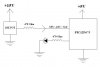
I wish to do a simple ADC experiment. Please see the enclosed diagram.
Before the PIC is placed in the circuit, the 10K pot is first trimmed to get steady 5.03V MAX output from the 15V DC supply which is a steady variable DC power supply. The 5V supply for the PIC is provided from 78L05 regulator IC. The ground reference is the same for the entire circuit.
Now when the 15V DC supply is at 15V MAX, the 10K pot output reads on volt meter as 5.03V. Similarly if the 15V DC supply is lowered to 10V, then the 10k pot output reads on the volt meter as 3.4V. I assume that these voltages are also seen by the PIC ADC pin (AN1) as shown in the diagram.
My program below simply checks to see that if the ADC voltage is equal or above 3.4V, then the PIC turns on the LED. If the voltage drops below 3.4V, then the LED remains off.
Sadly this is not happening and the LED remains on even if the DC supply is lowered down to 6V. Then the corresponding voltage out from the POT reads 2V. I have tried varying the "ADC_Result" variable value to a much higher vaule (800), but even that does not help and the same problem remains.
In the mikroC compiler, I have configured my project as....
CPD_OFF
CP_OFF
BODEN_OFF
MCLRE_OFF
PWRTE_OFF
WDT_OFF
INTRC_OSC_NOCLKOUT = ON
Below is my program. Please can someone help me to solve this problem.
Thank you
Haseeb
Im using PIC12F675 with internal OSC running @ 4MHz. Im using MikroC compiler version 8.2.
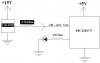
I wish to do a simple ADC experiment. Please see the enclosed diagram.
Before the PIC is placed in the circuit, the 10K pot is first trimmed to get steady 5.03V MAX output from the 15V DC supply which is a steady variable DC power supply. The 5V supply for the PIC is provided from 78L05 regulator IC. The ground reference is the same for the entire circuit.
Now when the 15V DC supply is at 15V MAX, the 10K pot output reads on volt meter as 5.03V. Similarly if the 15V DC supply is lowered to 10V, then the 10k pot output reads on the volt meter as 3.4V. I assume that these voltages are also seen by the PIC ADC pin (AN1) as shown in the diagram.
My program below simply checks to see that if the ADC voltage is equal or above 3.4V, then the PIC turns on the LED. If the voltage drops below 3.4V, then the LED remains off.
Sadly this is not happening and the LED remains on even if the DC supply is lowered down to 6V. Then the corresponding voltage out from the POT reads 2V. I have tried varying the "ADC_Result" variable value to a much higher vaule (800), but even that does not help and the same problem remains.
In the mikroC compiler, I have configured my project as....
CPD_OFF
CP_OFF
BODEN_OFF
MCLRE_OFF
PWRTE_OFF
WDT_OFF
INTRC_OSC_NOCLKOUT = ON
Below is my program. Please can someone help me to solve this problem.
Thank you
Haseeb
Code:
unsigned int  ADC_Result; //ADC result holding variable

void main(void)
{

    OSCCAL = 0x80; //trimming internal 4MHz OSC down to 'CENTER'

    GPIO = 0; //intiallize the port

    //intillize the Comparitor pins (GP0 to GP1) to Digital I/O pins
    CMCON  = 7;

    ADCON0.ADFM = 1;  //Result Right justified
    ADCON0.VCFG = 1;  // Voltage Reference is Vref

    // Channel 01 (AN1) SELECTED
    ADCON0.CHS1 = 0;
    ADCON0.CHS0 = 1;

    ADCON0.GO_DONE = 0; //Stop ADC Conversion
    ADCON0.ADON = 0;    //ADC Disabled

    //A/D Conversion Clock is FOSC/8
    ANSEL.ADCS2 = 0;
    ANSEL.ADCS1 = 0;
    ANSEL.ADCS0 = 1;

    //AN1 is Analog ..... rest all is Digital
    ANSEL.ANS0 = 0;
    ANSEL.ANS1 = 1;
    ANSEL.ANS2 = 0;
    ANSEL.ANS3 = 0;

    TRISIO.GP5 = 0; //LED output
    TRISIO.GP1 = 1; //Channel AN1 input

    INTCON = 0; //disable all interrupts
    PIE1 = 0;  //disable all peripheral interrupts

    ADCON0.ADON = 1; //ADC Enabled

    while(1) //loop forever
    {

        ADCON0.GO_DONE = 1; //Start ADC Conversion

        while (ADCON0.GO_DONE == 1);  //Wait until Conversion finishes

        ADC_Result = (ADRESH * 256) + ADRESL; //Merging High byte with low byte

        if(ADC_Result >= 696) // if we get 3.4V

           GPIO.GP5 = 1;  //LED on

        else

           GPIO.GP5 = 0;  //LED off

    }

} //end of main()