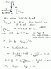
I think the whole argument is moot in that both circuits provided by Lj are essentially emitter followers. In the left diagram, a PNP transistor is shown, while the right uses an NPN.
For my projects using a transistor-driven LED, I generally use an NPN with 1K resistor on the base, put the LED in the collector lead with a 220 ohm resistor for 5 volts, or 470 for 9 V, resulting in a nice, bright LED.
As Nigel says, it isn't super critical.
AllVol