yes it work ( a little hard to set )
lets continue !")
OK,
Load, F9, run this button1.bas
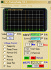
Select '8 LED Board', set the pins like this image.
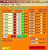
Run the 16F4Key2.exe module, set it like the image.
Use the buttons to light the LED's ,, play with inverted buttons and latching buttons,, OK.?
I have seen that the Blog exe has a colour change on two of the check boxes.?? its not a problem I will change it later.