Continue to Site

Welcome to our site!

Electro Tech is an online community (with over 170,000 members) who enjoy talking about and building electronic circuits, projects and gadgets. To participate you need to register. Registration is free. Click here to register now.

  • Welcome to our site! Electro Tech is an online community (with over 170,000 members) who enjoy talking about and building electronic circuits, projects and gadgets. To participate you need to register. Registration is free. Click here to register now.

PIC PWM and H-Bridge

Status
Not open for further replies.

camerart

Well-Known Member
Hi,

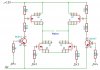
I am about to make a PIC driven H-Bridge circuit board. It needs to be able to switch each of the 4 Mosfets on/off individually.

Previously I made one that switch 2 mosfets each time. Using 'N' IRF7413ZPBF and P IRF7424PBF See attached SCH:

This works well, but now I need 4 switch circuit, if anyone has one please.

Also I have never used PWM for switching mosfets, has anyone got experience with fast switching of mosfets please.

Cheers, Camerart.
 

Attachments

  • Hbridge svg.gif
    Hbridge svg.gif
    16.1 KB · Views: 511
Your posted schematic is too low in resolution, and drawn in a convoluted way, to actually provide an opinion.
It appears though, that your upper Mosfets are always biased on.

Setting aside that, to control all Mosfets individually, you require a pair a things:
-a way to level shift the pwm drive signals for the upper Mosfets.
-a way to provide independent bias voltage for the upper Mosfets.

This can be done with discrete components, but to do "fast switching" (fast meaning how many Khz?) tailoring the individual component values is difficult to prevent shoot-thru and other faults that cause immediate and catastrophic destruction.
I can advise you to search on the International Rectifier's webpage and look for H-bridge drivers. Intersil also has a good selection.

Hi Schmitt,

I've re-sent the file as a gif, see if it's clearer. Sorry for the convolution, I draw in a way that helps me visualise circuits, (amateur:))

What happens is when one of the bottom 'N' type mosfets switch on, they pull down the gate of the top 'P' type mosfets to the required level, which switches them on.

The switching could be up to 720Hz. so it looks as if it's slow switching.

I have an idea, I'll draw and post later.

Camerart.
 
Hi,

I've moved some of the components from my 2 channel SCH, to make a 4 Channel version.

Does it look ok?

Camerart
 

Attachments

  • H-Bridge 4CH.jpg
    H-Bridge 4CH.jpg
    163.3 KB · Views: 779
Last edited:
Your High side FETS need a bit more voltage than you have got....

I found that you really need to use High side drivers..... The gate voltage needs to be higher than 12v for them to work properly.... Also you could do with a big cap across the power rails...

Hi Ian,

What are High side drivers? How do I get more than 12V from 12V batteries? Of course the 'P' mosfets can only be pulled down to 0V from 12V, in my SCH they only pull down to 6V. (This worked ok for simple switching, but I'm not sure about PWM)

C
 
Edited as it was false information.... Sorry about the confusion ( brain in gear before mouth)....

Also you do not want big gate resistance or the capacitance will cause issues.... Running a motor with a PWM of 20khz ( just above audible for teenagers ) I used 10 ohm gate resistors...

Also make doubly sure your FETs have flyback diodes built in, or you'll have to fit them externally...

I have built FET and TTL bridges... I must say the TTL one was FAR easier to control and manage... Running from the pic you can use the Enhanced PWM to make sure you dont short the FETS.... This has built in deadzones...
 
Last edited:
To fully open a P type MOSFET you need to raise the gate voltage above the source voltage..

What voltage are your motors.... If it is a 6v motor you could feed the source of the top fets 6v and control them with 12v... PWM usually is Max on Max off if you turn on your FET's in your example you wouldn't reach pinch off...

They recommend 10v above the source to fully turn on a P type MOSFET...

High side driver chips use a bootstrap circuit to generate this high voltage... As the current needed is very low simple components are used..

Also you do not want big gate resistance or the capacitance will cause issues.... Running a motor with a PWM of 20khz ( just above audible for teenagers ) I used 10 ohm gate resistors...

Also make doubly sure your FETs have flyback diodes built in, or you'll have to fit them externally...

I have built FET and TTL bridges... I must say the TTL one was FAR easier to control and manage... Running from the pic you can use the Enhanced PWM to make sure you dont short the FETS.... This has built in deadzones...

Hi Ian,

My motors are 12V.

I chose these mosfets because I was advised to get low RDSON ones, does this make any difference to the gate switch on voltage?

How I have understood the design: Is it true that as the 'P' mosfets are negative, and I pull the voltage down to 2v, then in a negative sense, this is 10v above the source voltage. Correct me if I'm wrong! So if that's correct, I need to change the transistor resistor values to bring it down (Up) from 6v to 10v. If this is correct, how does this workregarding the suggested 10 ohm gate resistor?

When I said 720Hz, I was getting mixed up with the quadrature encoder side, I'm sure the PWM will be as you say 20KHz.

The have internal flyback diodes.

Camerart.
 
Hi,

I was puzzled about the gate switch on voltage, and thought it a good idea to ask the Mosfet suppliers technical support for clarification.

Here's my question: "I am having difficulty reading the data PDF and setting the correct gate
switching voltage for 'P' Mosfet IRF7424PBF. Could you advice me please?"

The suppliers tech support reply: "Thanks - Its 1.0v min to 2.5v max."

Has this clarified or complicated things?

Camerart.
 
Ok..

Sorry I have completely missread...... I used four N type... for the lowest RDson.... You are correct.... I'm sorry for the jumbled post..

You dont need high side drivers for P types ignore my ignorance...

To achieve the highest voltage across the motor you need N types...... The gate resistance still needs to be relatively low because of the 20khz operation.... You don't need to run the PWM that fast but if you don't you'll hear the motors..
 
Hi Ian
Ok..

Sorry I have completely missread...... I used four N type... for the lowest RDson.... You are correct.... I'm sorry for the jumbled post..

You dont need high side drivers for P types ignore my ignorance...

To achieve the highest voltage across the motor you need N types...... The gate resistance still needs to be relatively low because of the 20khz operation.... You don't need to run the PWM that fast but if you don't you'll hear the motors..


Hi Ian,

As long as we get there in the end:)

So bearing in mind these are fairly modern low RDSON 'P' types, that I used for the upper ones, and similar matching 'N' type for the bottom ones. If you were starting again would you use 2 and 2 or 4x 'N' types?

If so, why would anyone use 'P' types?

C.
 
I know that N types have the lowest RDSon resistance.... The company I have designed this thing for needs the full speed available as its geared to hell.....

You will probably find that these will be as good as...
 
..........................
I was puzzled about the gate switch on voltage, and thought it a good idea to ask the Mosfet suppliers technical support for clarification.

Here's my question: "I am having difficulty reading the data PDF and setting the correct gate
switching voltage for 'P' Mosfet IRF7424PBF. Could you advice me please?"

The suppliers tech support reply: "Thanks - Its 1.0v min to 2.5v max."

Has this clarified or complicated things?
Tech support has muddled things. He made the newbie mistake of giving you the threshold voltage which, as the data sheet shows, is the voltage where it just starts to turn on at a drain current of 250μA.

If you look at the Rds(on) value you will see that it requires Vgs = -10V for an On-resistance of 13mΩ and Vgs = -4.5V for an On-resistance of 22mΩ. Thus you want at least -4.5V for Vgs to fully turn on the MOSFET and -10V if you want the minimum ON resistance.
 
hi Carl,
The motor is only a 12V 10W 1.6A Parvalux.

The OP has been given a circuit diagram, checked using LTS, on another Forum.

Eric
 
hi Carl,
The motor is only a 12V 10W 1.6A Parvalux.

The OP has been given a circuit diagram, checked using LTS, on another Forum.
I don't see how either of those facts affects my answer. :confused:
 
hi Carl,
The motor is only a 12V 10W 1.6A Parvalux.

The OP has been given a circuit diagram, checked using LTS, on another Forum.

Eric

Hi Eric,

I designed the circuit in #1 from Information at the time, 4 years ago, which uses the 'N' channels to pull the 'P' channel gates down (negative up) at switch on. This is the one checked using LTS and is switched by 2x Channels.

What I am researching here is a new individual 4 channel switching one show in #5 (needed if braking is needed in the future), this one hasn't been checked yet, and I'm checking the transistor switching of the 'P' channels.

C.
 
Last edited:
Tech support has muddled things. He made the newbie mistake of giving you the threshold voltage which, as the data sheet shows, is the voltage where it just starts to turn on at a drain current of 250μA.

If you look at the Rds(on) value you will see that it requires Vgs = -10V for an On-resistance of 13mΩ and Vgs = -4.5V for an On-resistance of 22mΩ. Thus you want at least -4.5V for Vgs to fully turn on the MOSFET and -10V if you want the minimum ON resistance.

Hi Crutchchow,

Four years ago, I could understand the data sheets better:(

Thanks for spotting this. I'm a bit lost with the On-resistance information. As you can see I used the same 'P' channels switch on resistors as in SCH #1, this brings the gate voltage down (negative up) to 6V. Should I change them to pull them down to 10V (negative up) gate voltage. ( I use the negative reminder, as it is a bit complicated using negatives for newbies, and me)

Would you be good enough to also check the 'N' mosfet data sheet for me please, or does the TTL value switch these ok? I assume it is ok, because I've been using SCH #1 circuit for years. 'N' IRF7413ZPBF and P IRF7424PBF

C.
 
Last edited:
I don't see how either of those facts affects my answer. :confused:

Carl.
It does not affect you answer.

I was simply pointing out that the motor is light weight and the previously suggested FET's are more than capable of the driving that motor.
[FDS6575 & IRF7201 ]
My answer was intended to give you more information about the motor, and the single +12V supply.

Eric
 
...............................
Thanks for spotting this. I'm a bit lost with the On-resistance information. As you can see I used the same 'P' channels switch on resistors as in SCH #1, this brings the gate voltage down (negative up) to 6V. Should I change them to give a -10V (2V negative) gate voltage. ( I use the negative reminder, as it is a bit complicated using negatives for newbies, and me)

Would you be good enough to also check the 'N' mosfet data sheet for me please, or does the TTL value switch these ok? I assume it is ok, because I've been using SCH #1 circuit for years. 'N' IRF7413ZPBF and P IRF7424PBF
The On-resistance information tells you what gate-source voltage the manufacture uses to characterize the on-resistance. That means you should not normally use less than that if you want the MOSFET to operate as a switch with a low on-resistance.

Both the transistors you listed are characterized at both a Vgs of 4.5V and 10V so you can use either value, depending upon how low you want the on-resistance to be. Thus 6V for your circuit should be fine unless you want the absolute lowest on-resistance.

If you operate the N-MOSFET from a TTL output, which is typically only about 3V, you should add a pull-up resistor (say 1k) from the TTL output to the +5V voltage so that the gate voltage goes to 5V when the transistor is on.
 
Status
Not open for further replies.

Latest threads

Back
Top