Wond3rboy
Member
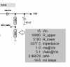
Hi i was about to check the working of the 18F1320's ADC when i read in the datasheet that the maximum impedance of the analog source allowed is 2.5kohm. I was about to do it with a 10k potentiometer.Do i need some external circuitry? But how can we reduce the impedance of the source?
")