Continue to Site

Welcome to our site!

Electro Tech is an online community (with over 170,000 members) who enjoy talking about and building electronic circuits, projects and gadgets. To participate you need to register. Registration is free. Click here to register now.

  • Welcome to our site! Electro Tech is an online community (with over 170,000 members) who enjoy talking about and building electronic circuits, projects and gadgets. To participate you need to register. Registration is free. Click here to register now.

Pic Development Board

Status
Not open for further replies.

bryan1

Well-Known Member
Hiya Guy's
Well after my last attempt at buying a development board I've decided to try and make my own. here is a link to the **** I paid good money for but was lucky to get my money back and keep the useless board.

https://www.electro-tech-online.com/threads/how-does-4x4-keypad-work.16629/

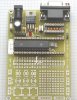
Now I would like to make my own development board as I have all the equipment and resources to etch my own board. Now can anyone give me an insight to a board they have made as to start my thinking?

One thing I have noticed on every board I've looked at is they always hog certain ports for phericals like LCD's and 7 segment displays. I do have a few idea's on a new board but any inputs would be greatfully apprecieated.

Cheers Bryan :D
 
Last edited by a moderator:
Any development board is always going to be restrictive, I would suggest making small modular boards like my tutorials use - this allows far greater versatility as it's permanently expandable.

But the board you bought looked pretty good, what was wrong with it?.
 
Hiya Nigel,
well for the board several joints were dry soldered and the rs-232 wouldn't work even after changing the max chip and re-programming the bootloader into a fresh 16f877a, many caps and resistors were missing and there wasn't any documentation with the board although oshonsoft did supply one after two weeks, and looking at the schematic I did see the 7 segment display and the lcd collided.
Anyway in the next few days I have a stab at my own and post up my efforts. Nigel, thanks for the tutorials and boards and I've made a few but as I have a few 12"x12" copper boards laying around it's time to make my own.

Cheers Bryan :D
 
Bryan,

Nigel is correct... Too much "stuff" on a single board is not always the best way to go...

Here's a picture of a 28-40 proto' board I designed when getting started almost 2 years ago...

Regards, Mike
 

Attachments

  • proto_28-40_board_134.jpg
    proto_28-40_board_134.jpg
    51.1 KB · Views: 2,123
Mike,

Are the four holes at the sides of the ground plane for the crystal for caps? Looks like the middle three holes are for a ceramic resonator, with the center hole for ground. And the holes at the sides probably connect to the crystal on the underside?

Mike
 
Neat design Mike. Would you happen to have the PCB layout in some printable file format?

Mixing your board with Nigel's small boards and a solderless breadboard area would make an ideal all-around solution IMHO, at least for me.
 
Hi Joel,

I've got the ExpressPCB layout for that board if you'd like... If you download the ExpressPCB program from ExpressPCB.com, you'll be able to load and then look at the layout... I think I paid $59USD for three boards from them...

Regards, Mike
 
Hiya Guys,
Well it took me a few hours work but below is etching pattern for the development board I've designed. If you can take a look at the drawing and see if I made any errors I'll appreciate it as this is my first attempt at this sort of thing. With the reset circuit I got that straight from the 16f877a datasheet and I'm not sure if I have the resistor values correct. Hopefully I have everything correct.

Cheers Bryan :D
 

Attachments

  • development_board.gif
    development_board.gif
    19 KB · Views: 1,867
Hey Bryan! Looking good for a first effort.

I might be full of baloney, but to me the 820 ohms resistor in series with the 10K is useless. What is it for?

You sure that 7805 is hooked up correctly? My batch of 7805 uses pin 1 as input, pin 2 as ground and pin 3 as output. So in my case, your circuit would be wrong (pins 2 & 3 reversed), but maybe your 7805s are different?

Apart from that, it looks damn good!
 
Hiya Joel,
Thanks for pointing out the regulator, you are correct, silly me never checked the pinout with the data sheet I just used the labelling straight off the macros. As far as the mlcr circuit, below is an excerpt from the data sheet and I just used the first resistor under 1 K in the drawing. By the way Im using sprint layout software which is a good program in my opnion.

Cheers Bryan :D
 

Attachments

  • mlcr.gif
    mlcr.gif
    10.8 KB · Views: 1,591
One suggestion you might think about?, in my tutorials I use 10 pin connectors for ALL ports, with 0V at one end and 5V at the other, this is EXTREMELY useful, and well worth considering.

You might also notice that I try and move all the I/O sockets to be together, and the same way round - it's not easy on veroboard, but should be a lot simpler on a PCB. Again, it's a little point, but it makes life just a little easier :D
 
Hi Bryan1,

Regarding the MCLR pin:

In your layout you are connecting/disconnecting the pin from the rest of the circuit.

You should really connects the switch between junction of 10K and capacitor and ground.
 
eblc1388 said:
Hi Bryan1,

Regarding the MCLR pin:

In your layout you are connecting/disconnecting the pin from the rest of the circuit.

You should really connects the switch between junction of 10K and capacitor and ground.

Does this mean I can delete the 820 ohm resistor ? I thought I made it to suit the picture shown in the data sheet.

Cheers Bryan :D
 
Hiya Guys,
Many thanks to Nigel for suggesting putting power and ground lines on the port output pins :D , also thanks to L.Chung for putting me in the right direction on the mlcr circuit :D . Well I started from scratch and below is a copy of mark II of the board. I've spent hours going over it and can't see any errors so hopefully it's ok.

Cheers Bryan :D
 

Attachments

  • development_board_1.gif
    development_board_1.gif
    21.7 KB · Views: 941
Hi Bryan1,

In you second layout, the +5V does not reach 877 and the port pins. It stops at the MAX232.

In addition, I can't tell from the gif whether you have connected 0V of MAX232 & the rest of the circuit to the 7805(note the white trace).

Also check the polarity of capacitor on MAX232 pin2.
 

Attachments

  • board_1.gif
    board_1.gif
    21.9 KB · Views: 920
Thanks for pointing out those errors on the board L.Chung, after spending about 4 hours working on it those simples things seem to slip through. After taking a closer look I also had a few other caps wrongly polorised and how I managed to forget the power to the pic ( well it was a long night). Anyway I'll have a go with the press-n-peel paper tomorrow and get the board made up, and thank you for the support mate greatly apprecieated. :D

Cheers Bryan :D
 
Status
Not open for further replies.

Latest threads

New Articles From Microcontroller Tips

Back
Top