Continue to Site

Welcome to our site!

Electro Tech is an online community (with over 170,000 members) who enjoy talking about and building electronic circuits, projects and gadgets. To participate you need to register. Registration is free. Click here to register now.

  • Welcome to our site! Electro Tech is an online community (with over 170,000 members) who enjoy talking about and building electronic circuits, projects and gadgets. To participate you need to register. Registration is free. Click here to register now.

PIC-chronograph trouble

Status
Not open for further replies.
Alright, so here is my problem.

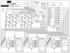
I've been working on this chronograph which uses a photogate system to measure the speed of an object that flies through the two gates.
I've gotten most of the final program for that taken care of. However, because it is the first of it's type I made a very short program which would allow testing of all of the various inputs and outputs.

I know that there are many problems already, but I just figure that I would go down the list.

all three of the 7-segment display's and their drivers are working properly


here's the problem I'm trying to figure out right now...I can't get any of the inputs to function properly, specifically any of PORTE. the circuitry with the three switches does what it is supose to do, leading me to believe that it is a programming issue.

Attached is the circuit diagram and the current program

If anyone does notice a problem with the circuitry please tell me as I still can make minor changes, but I already have a PCB made. (the circuit is currently on a breadboard for testing)

Any ideas on what the problem could be?
 

Attachments

  • PICCHR2T.asm
    5.1 KB · Views: 185
  • PICChrono2.jpg
    PICChrono2.jpg
    515.4 KB · Views: 339
do you switch off the A/D?
i think 16f877 has A/D on PORTA.

also have you considered a multiplexed LED display?
 
do you switch off the A/D?
i think 16f877 has A/D on PORTA.

also have you considered a multiplexed LED display?

what is A/D?

Though there is a problem with the two inputs on PORTA, I don't think that it is the PIC in that case. I'm trying to at least get the inputs on PORTE to function before I move on to the main optocouplers.


Also, the first design had the three segments run off of one pin on a smaller PIC, but that would only allow the display of numbers.

EDIT----just looked at the datasheet. all of the A/D control bits are automatically set to be disabled during start up if you leave them alone
 
Last edited:
Take a look at this if you haven't
The PORTE pins become the I/O control inputs for the
microprocessor port when bit PSPMODE (TRISE<4>) is
set. In this mode, the user must make certain that the
TRISE<2:0> bits are set, and that the pins are configured
as digital inputs. Also ensure that ADCON1 is configured
for digital I/O. In this mode, the input buffers are TTL.
you don't have porta or porte set to digital i looked at your code
 
Last edited:
EDIT----just looked at the datasheet. all of the A/D control bits are automatically set to be disabled during start up if you leave them alone

At power up all analogue capable pins are set to analogue and will not function as digital inputs. You need to write 0x06 to ADCON1 to make them all digital.

Mike.
 
Mike you beat me to it I just downloaded the data sheet to see what PORTE needed to be set to.
just looked at the datasheet. all of the A/D control bits are automatically set to be disabled during start up if you leave them alone
Not
with a pic It just like Mike said
At power up all analogue capable pins are set to analogue
It also works better if you set your (tris) first then (clrf) the port
 
Last edited:
COOL!

thankyouguys for the help, I'm inserting the segment of code

MOVLW B'00000110'
MOVWF ADCON1

into the "INIT" label (in the proper bank) as well as clearing the ports after the tris have been set for each port.


one quick question though,

Will setting the ADCON1 register affect RA1 and RA0 as they are being used as outputs?
 
Will setting the ADCON1 register affect RA1 and RA0 as they are being used as outputs?
nope you want it all digital that it dos it turns off adc so you can use the porta as output or input pins
 
COOL!

thankyouguys for the help, I'm inserting the segment of code

MOVLW B'00000110'
MOVWF ADCON1

into the "INIT" label (in the proper bank) as well as clearing the ports after the tris have been set for each port.


one quick question though,

Will setting the ADCON1 register affect RA1 and RA0 as they are being used as outputs?

Note that ADCON1 is in bank 1.

Mike.
 
and.......IT WORKED!!!!

thankyou again guys for all of your help

it all worked as it should, except for one of the gates, but I'm pretty sure it's just a short or this ancient 4072 has a problem. (made in 1986, and the casing looks kinda iffy)

if it is something else I put up another question in this thread.
 
Hah, there wasn't a short nor was there a problem with the OR gates. I forgot to set all of the 100ohm trimpots to about halfway. There was one on the assumed failing gate that didn't have enough resistance to keep the OR gate from tripping

So luckily, I don't have to remove any of the traces from that already made PCB

here's a few pics of the board and its enclosure/custom photogate housing

**broken link removed**

**broken link removed**
 
well, the board has been soldered, tested, and worked perfectly, gate's and all.
It has been cased and is pretty much ready to go save for a few actuators for the input buttons and the lid needs a few more holes.

I've been working on the final firmware for the device, except I can't seem to figure out where these glitches are coming from.

sometimes it's pretty dang accurate, and sometimes its pretty far off.

I know it is pretty much impossible to put this on the internet and have it magically fixed, but is there any segment of code that doesn't quite look right to anyone that could be causing a problem?

To store the required numbers, it uses set registers representing numeral places that within the code will never hold anything greater than 10 in decimal. when they reach 10, they are cleared and the next register up is incremented.

the code follows this algorithm in order to get a velocity from the gate system:


x= measured time
xp=x/100

q=# of times x is added onto itself

xp is added to itself q number of imes until the result is equal to or greater than 1

q is then divided by 100 to give the final answer

all of this divides 1/x
 

Attachments

  • CHRONO_FINAL.asm
    23.6 KB · Views: 185
I haven't looked at your asm, but from your algorithm there are 2 potential problems;

1. the xp sequential addition should never exceed 1, it should stop as close to 1 as possble but still be <1 or =1.

2. What is the smallest expected value of x? You are damaging accuracy by doing the x/100 operation and then even worse later when you do q/100. To fix that you should leave x undamaged, and add x to itself until it reaches a high decimal number (up in the millions is best) so you have a value of q that has a higher resolution. If you pick the high number based on your processor speed and snesor distance you will get a q value that is directly in feet per second or metres per second.

To debug the hardware and the sensor firmware you can just mod the firmware to display x on the display, ie just display the elapsed time directly (value in the PIC timer). You can then check your hardware is not jittery, likewise they way you are reading the timer etc. When that is going good you can add in the math part to convert elapsed timer ticks into FPS etc.
 
I can see why xp*q should be ≤ 1 I'll try to change that. The easiest way I can see this being possible is to insert a code after it has finished incrementing q. It will test the contents of zplace (xp added onto itself in the program). It will test every place except for zplace_1. If the rest of the places hold any number, q will be decremented by 1

The x/100 was to try and allow much slower speeds to be measured. Say for example the gates record a time of 7 seconds. It would then be divided by 100 giving .07 (in the pic, the numbers would just be shifted)
.07 would then be added onto itself until the result would be ≥ 1( which will soon change to ≤1)
When x added onto itself (zplace in the program) would get to 1.05 (soon to be .98, q would equal 15 (soon to be 14. From there, q would be divided by 100 to give .15 (soon to be 1.4, where 1/7=.142857...
 
Well, the program's ability to select between speed and time is fixed. When it's just recording/displaying the time it's pretty accurate (given the time is less than 9.9999seconds)

The speed is still giving me some problems though.
 
ok, so I think I may have found a problem, but it brings up two questions I have that for some reason google and many pic-programming tutorials haven't been able to answer.

say I'm using the MOVF command in the example below

MOVF COUNT, W

after it's moved the stored number in the register to the W register, does the number in the COUNT register stay the same?


very similar to the above question say I'm using the below example to set the Z flag


MOVLW D'10'
XORWF COUNT, W

again, would the number in the count register after the XORWF command be the same as it was before the command?
 
In both examples the value in COUNT will be unchanged. In the second example, if you did XORWF COUNT,F then W would be unchanged as the F tells the processor to store the result in the file - COUNT.

Mike.
 
awesome, that is exactly what I was counting on.

these weren't the problem, but I found two specific segments of code that were creating the problem.


one was as it added the different places of xsplace to zplace, I had it set to increment z and decrement x before it tested if the register was already set to zero--meaning that if the bit it was testing was at zero, it would ignore this, and decrement the bit to 255, throwing it way off. This has been fixed


the second was when it was adding the numbers together to reach 1. it would only test it at one moment in the code for one specific number. there was a possibility for more than one in that partictular register. This has also been fixed


and now IT WORKS (well it can measure speed and time)

I still need to make the code a bit more user friendly, but at the moment it does what it is intended to do

:D Thankyou guys for you help, again. Without it, I would have had to settle for a simpler code (deadline for this project is in 3 days)


a video link will follow soon in a few days.
 
Status
Not open for further replies.

Latest threads

New Articles From Microcontroller Tips

Back
Top