Continue to Site

Welcome to our site!

Electro Tech is an online community (with over 170,000 members) who enjoy talking about and building electronic circuits, projects and gadgets. To participate you need to register. Registration is free. Click here to register now.

  • Welcome to our site! Electro Tech is an online community (with over 170,000 members) who enjoy talking about and building electronic circuits, projects and gadgets. To participate you need to register. Registration is free. Click here to register now.

PIC based high-resolution cap meter

Status
Not open for further replies.
Hi, I have done a PIC 16F628 based pico-capacitance meter.

I know there are a lot of other designs around but this one is very quick to build as it just uses one IC, the PIC (as it uses the PICs internal comparator as the oscillator).

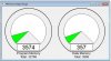
It measures down to 0pF and reads in 0.01pF resolution in the bottom range, up to about 18000pF.

Total measuring range is 0pF to 50uF. It only needs a decent 10k 1% resistor and will be calibrated so ideall you won't need any special caps or test equipment to build it.

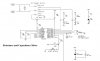
The schematic, PIC HEX file and photos etc are all here;
https://www.romanblack.com/onesec/CapMeter.htm[/b]

**broken link removed**


**broken link removed**


very nice project . how can modified it for reading up to 4700mfd ? & also reading for resister ?
 
Atom, why do your own version when mine is fully finished and tested and the PIC hex file is included? There were a few clever firmware tricks I used to ensure very high resolution and math precision, and it was not easy to fit it all in a 2k PIC. It has also had quite a bit of testing against good frequency meters and other cap meters. Why try to duplicate tricky hard work when it's already been done for you? :eek:

Sahu, most multimeters read large capacitor values, it is the small caps that can be hard to read. Also large caps are very clearly marked so is never doubt as to what their value is. :)
 
Last edited:
Atom, why do your own version when mine is fully finished and tested and the PIC hex file is included? There were a few clever firmware tricks I used to ensure very high resolution and math precision, and it was not easy to fit it all in a 2k PIC. It has also had quite a bit of testing against good frequency meters and other cap meters. Why try to duplicate tricky hard work when it's already been done for you? :eek:

Sahu, most multimeters read large capacitor values, it is the small caps that can be hard to read. Also large caps are very clearly marked so is never doubt as to what their value is. :)

Roman, dont be offended in any way... i simply dont own any 16F628's and i wanted to see if i can do it also. Its not a clone of your work at all. I can draw you a schematic if you want. my code is also small.

Its less than 4k which is good for most PIC18F series. Also i might make it USB so you get the value in a nice windows application
 

Attachments

  • codeu.jpg
    codeu.jpg
    33.9 KB · Views: 617
Here one I been playing with Resistance and Capacitance Meter from a appnote

I changed it to use a LCD working on a way to read inductors
 

Attachments

  • Resistance and Capacitance Meter.jpg
    Resistance and Capacitance Meter.jpg
    47.9 KB · Views: 1,210
Roman, dont be offended in any way... i simply dont own any 16F628's and i wanted to see if i can do it also. Its not a clone of your work at all. I can draw you a schematic if you want. my code is also small.

Its less than 4k which is good for most PIC18F series. Also i might make it USB so you get the value in a nice windows application

I'm not offended! The reason I put hobby work up on my web page is so people can enjoy it and benefit from it. :)

It's great that my little cap meter is of interest to people and might even inspire them to build their own, and it would be fun to see people's designs and look at the pros and cons of each design.

It was just based on your earlier posts I thought you were using my design of the comparator oscillator and accumulated consecutive periods etc, and it just seemed to me that if you were going to copy 90% of my design then why not just use the firmware too as it was carefully tested. :)

Burt, I tried making an inductor meter using the RL comparator oscillator but there are significant problems. Most inductors require a minimum current for their core magnetics to start to work properly, so my attempts using 5mA for the inductor oscillator proved pretty bad.

Most inductor meters use an LC resonance oscillator, which works well but unfortunately requires a square root in the L calculation as freq (or period) is proportional to square root of LC. BillMarsden on the other forum was making an RL oscillator for period inductance measuring but using a FET to get enough current to work the inductor. There's an interesting thread there.

Of course the PIC can do a square root etc but it really starts to cause some problems if there is a very wide range of inductance value. As my RC cap meter is linear it copes well with the huge measuring range of 0.01pF to 50uF (that's 5 billion to one!) but with an LC meter and square root it needs to a much smaller limited range and then needs hardware range switching etc.
 
Last edited:
Sahu, most multimeters read large capacitor values, it is the small caps that can be hard to read. Also large caps are very clearly marked so is never doubt as to what their value is. :)

no sir , my doubt for weakness for old large value caps.
 
Hi Roman,

You've forgot to mention what is the RC oscillator frequency : " The oscillation period (freq) is set entirely by RT and CT. "

Is the duty cycle 50% ?

Thank you !
 
Hi Hugo, I did say on my web page near the bottom under the heading "Testing";
"When it powers up the display will read the total value of the internal 270pF cap plus some extra capacitance from PCB tracks etc. Mine reads about 320pF. The oscillator will be running about 220 kHz."

Then as more capacitance is added the frequency will drop accordingly.

Yes the duty cycle is very close to 50%.
 
That helps but I was expecting a mathematical formula, something like this : T= K*RT*CT ; K = constant ;

is it by any chance T = 1.4*RT*CT ?
 
Last edited:
For those few guys who have tried this circuit on another device other than the '628A, may I ask which comparator configuration you used, please?

TIA. Regards, Mike
 
Hugo, the constant depends on the amplitude the comparator switches between. In my original version the comparator resistors set the switching points at 1/3 Vcc and 2/3 Vcc so it is the time RC takes to charge and discharge between those 2 points. It was easiest to measure known 1% caps against the period and manually enter the constant in the source code. I've since found some 0.5% caps and they test good too so my constant must be pretty close! If you are using my hex file and wanted to "trim" the constant you can do that in hardware; either trim the 10k resistor or trim the 1.5k on the comparator output (between RA3 and RA2).
Both those resistors have an effect on the frequency of the oscillator (for a given cap).

Mike, I didn't try on a PIC other than 16F628A but the comparator setup was the one that allows all 3 pins of the comparator as external pins (I think there's only one mode like that?), then the external pin for comparator output was tied through a resistor into the CCP capture input, to capture the period. You could use an external comparator if needed.
 
Last edited:
Hi Roman,

Thanks for sharing your project and other very interesting ideas. How exactly does the cap meter work? Your explanation on your website is confusing me a bit. Some psuedo code might help....

I have done a frequency meter in the past but would like to understand your method of doing things, if it is indeed any different from what I did.

"The PIC measures the RC oscillation period by using the PIC's internal hardware capture (CCP1). The PIC xtal is 16MHz so the PIC timer runs at 4MHz.

It adds consecutive captured periods until there is a total accumulated time greater than 2 million counts (>0.5 second). The only error can be the edge error for the first and last capture, so the error is limited to 1 part in 2 million at each end, a total possible error of 1 PPM (1 Part Per Million).

Now it has a precise captured total of periods the average period is determined by dividing the total period with the number of periods captured. As the total is always just over 2 million it is scaled up to 2 billion before the division, to give a lot of accurate decimal digits after the division."
 
While I'm at it I might as well post more details on the application. I made a simple capacitance water level sensor using water as dilectric and one bare and one insulated wire. Tha change in capacitance changed osc frequency of 555 which was fed into pic CCP. problem was that PIC had to run at very high frequency (about 40Mhz) to be able to get nice resolution and probe also soon ran out of range. Thus the overall project worked but resolution was not that great.

I'm thinking that you might have a better way of indirectly measuring the capacitance which might benefit my application. I can't recall all the details of the project as it was completed a few years ago but the capacitance of the probe was very small (20pf range if I remember correctly) and the change was also not that much. The idea is to implement the "new" design in a 12F675 or 12F683 with internal osc if possible. The less external components the better...

Regards
 
Hi Crystallattice, the Cap meter is not a frequency meter really but a "period meter". This is because a larger cap causes a larger period, reasonably linearly. So all you do is measure the oscillation period, and scale it by a single scaling factor and you have a reading in capacitance.

I thought it was already explained pretty good on my web page. :)

The same principle should work ok for your capacitance probe, ie measure period, scale to capacitance (or directly to water level if that is linear to its capacitance). It sounds like an interesting project, you should start a thread on the water level meter project so people who are interested in doing the same water level project or who have experience in that specific area can get help from the thread or contribute to it etc. :)
 
Thanks Roman, but you are still leaving me in the dark...

In my original design I used the CCP to capture internal tics from tmr1(running at 10MHz). The CCP was fired on every 16th edge of the 555 osc output, this ensures that there are enough tics as the signal was quite fast at some point (KHz range). This was allowed to happen for exactly 1 second and all the tmr1 overflows were also counted. Combining the overflow count and the current CCP count you can get a very nice indication of the period of the 555 signal. So yes, I measured the period of the signal instead of the "frequency" per se.

The way you explain it, or rather the way I (mis?)understand it, is you are doing something similar but not sure what you mean by the 2 million cycles thing? Please explain the following:

"It adds consecutive captured periods until there is a total accumulated time greater than 2 million counts (>0.5 second). The only error can be the edge error for the first and last capture, so the error is limited to 1 part in 2 million at each end, a total possible error of 1 PPM (1 Part Per Million).
"

The biggest problem I had with my probe was the small change in capacitance over the length of the probe - 2000mm or rather the inability to measure it. Redesigning the probe with better materials would probably yield a larger delta C but given the time and resources that was never materialised - know of any good source of very thin (or very thinly coated) PTFE/teflon coated wire?

I must really scratch and find my documentation to see what values I got but it was the main cause I did not develop the project further, the other was that the project was the end of my studies for which I got a distinction and was fairly happy with that!

Looked at other methods of measuring capacitance on the PIC and it would seem the "frequency conversion" method is the most "accurate" for my application although there are better solutions than to use a 555 - like what you did.

I will probably share the code in the future, but will try and see if I can't market it locally first to try and make a few bucks.... it seems the new trend is to design something and start a company! Not that I think something like this will ever get that big, but no harm done in trying to pay for my time...

Regards
 
It sounds like you know what you are doing with the softwarer side. :)

Maybe you're right a probe redesign might be the best option? Sorry I don't have a lot of experience with capacitance probe water level detectors.
 
Hi Roman,

GREAT project! I've been looking for a schematic for one of these! Perfect timing! I'll post when I get it up and running.
Thanks for sharing your work!

~ Jon G.
 
Status
Not open for further replies.

Latest threads

New Articles From Microcontroller Tips

Back
Top