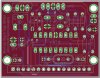
The board is looking good Atom! This is fun.
")
I still have some suggestions (haha);
1. adding another trimpot to let the user do global calibration is a good idea. Please see what i said in post #17.
2. The button on PCB may be under the LCD? I still think the button is better OFF the PCB as they can position it nice on front panel. Then the space on PCB can be used for that 2nd trimpot.
")
3. Does it really need the ICSP connector? With through hole they/you can program the PIC and plug it in a socket. Removing ICSP connector makes the PCB simpler and smaller and probably makes routing easier.
I just measured two adjacent empty rows on a solderless breadboard (5holes/row) and they measured 3.1pF. Much less than I expected! Maybe it is double that or more depending what is on each side of a row (what is plugged in).
In the past when I have used xtals in breadboards I left out the 22pF caps and it always worked ok.
Burt, did you remove the link for the video? I can't see it on this page but maybe it's my clunky old web browser...
(edit) Can that last statement I had Flash turned off in my browser. I was able to see your vid from the url;
https://www.youtube.com/watch?v=9FZDP-8Osyk
If that 107pF is the base reading (ie C1 and all the wires etc) you can zero it out by pressing the zero button (or short PIC pin RB2 to GND).

 Also shouldnt you be able to zero it out ? if so can you connect it via wire and zero out before connecting both ends?