Hi,
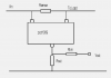
I read in the 16f877a PIC datasheet that the I/O pins have internal diode protection to limit the input voltage to +/- 0.6V from Vdd and Vss.
Does that mean that if my analog input exceeds 5V, the diode will become forward bias, and clamp it to 5V, so that the ADC will be reading 1023 (for a 10-bit resolution)?
I was actually planning on having a zener diode in parallel with my ADC input, but it seems like that would be redundant.
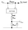
I can't seem to find the specs of those internal diodes. What is the max voltage that the diodes can handle. I would like to add a resistor in series with the input just to ensure that my input voltage never exceeds the max voltage that the diode can handle.
I read in the 16f877a PIC datasheet that the I/O pins have internal diode protection to limit the input voltage to +/- 0.6V from Vdd and Vss.
Does that mean that if my analog input exceeds 5V, the diode will become forward bias, and clamp it to 5V, so that the ADC will be reading 1023 (for a 10-bit resolution)?
I was actually planning on having a zener diode in parallel with my ADC input, but it seems like that would be redundant.
I can't seem to find the specs of those internal diodes. What is the max voltage that the diodes can handle. I would like to add a resistor in series with the input just to ensure that my input voltage never exceeds the max voltage that the diode can handle.