Continue to Site

Welcome to our site!

Electro Tech is an online community (with over 170,000 members) who enjoy talking about and building electronic circuits, projects and gadgets. To participate you need to register. Registration is free. Click here to register now.

  • Welcome to our site! Electro Tech is an online community (with over 170,000 members) who enjoy talking about and building electronic circuits, projects and gadgets. To participate you need to register. Registration is free. Click here to register now.

PIC 18F4550 Temperature Controller Project Assistance

Status
Not open for further replies.

Micro9900

New Member
Hello, my project entails outputting the temperature to an LCD display. I already have the LCD display working thanks to all of your assistance in a previous thread.

I will be using a PIC18F4550 using MPLAB v8.76 with C18 Lite compiler (for programming in C).

The sensor I will be using is a NTC (Negative Temperature Coefficient) thermistor. According to the data sheet (posted below)

Model #: NTSD1XH103FPB30
Datasheet: https://www.electro-tech-online.com/custompdfs/2011/10/NTSD120Spec.pdf
(see chart on page 3/5 and look under NTS__XH103 at 10K)

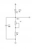
The setup I am planning on is illustrated below:
**broken link removed**

The main problems/ questions are as follows:
___________________________________________
1. What additional connections should there be if any? (Can I just connect Vout to RA0/AN0 of the microcontroller?)

2. There is a chart on page 3 of 5 of the datasheet. Can that be useful in determining the voltage at each temperature (using 5V and the various resistances listed at each temperature)?

3. What should the basic setup of a program like this be (What does ADCON have to be setup as, and how is the equation setup)?

If anyone can answer any of the above three questions that would be greatly appreciated. Thank you.
 
Last edited:
May I ask, what temperature range you need to read? If it is in the range -55°C to +125°C (-67°F to 257°F) then I would suggest using something like a DS18B20 as it will give greater accuracy and be easier to program.

Mike.
 
Thank you for the prompt response. I'm using this for average temperatures around the house or outside (winter/summer). I'm not going to measuring anything too hot or too cold. I just want to demonstrate that it works. I would say 0ºC (32ºF) to 38ºC (~100ºF) would be good.

What I am considering is driving a fan if the temperature goes above a set amount. I will probably use a blowdryer to simulate an increase in temperature and then activate the fan.

Edit1:
If it really is that easier to program and if you can help me a bit more with the DS18B20. I would get that. I've read a bit more on thermistors, but I do not have a preference as I would just like to understand how the device works and if I can implement it within a timely fashion.

EDIT2:
I have located the part on digikey is this acceptable?

http://search.digikey.com/us/en/products/DS18B20+/DS18B20+-ND/956983
 
Last edited:
If you say a range of 0 to 50C then you will have resistance of 4161 to 27219. Picking a resistor in between these values of 15000 would give ADC readings of 660 to 222. Your biggest problem is the fact that the device is not linear and so you will need a lookup table for the other temperatures.

The DS18B20 just gives you the temperature as a number. I think I have the routines to read one (or many) somewhere.

Edit, you may need to buffer the above circuit with an opamp but you may get away with a high quality 0.1nF ceramic capacitor to ground.

Mike.
 
Last edited:
DS18B20 just gives you the temperature as a number.

Wow, that certainly seems like a more efficient and a more manageable approach. I'll think I will go that route. If you provide some insight as too what the requirements of the DS18B20 in terms of connections and programming that would assist me greatly. This is of course a big part of the project. The quicker I can get thinks going, the better. Thank you so much.
 
I did a little project using the DS18s20 (See clicky). That is in assembly but if you don't implement the ROM search routine (means having 1 pin per sensor) the routines will be pretty simple in C18. I won't have time until maybe Sunday (demanding girlfriend) but then I should be able to find my C18 routines. I may have even written the ROMsearch routine so you can have multiple chips on 1 pin.

Mike.
 
No problem. Thank you so much for the foresight. I'll post later this week once I get the part. And thank you again for taking the time to respond.
 
Hi,

To answer your original question, the circuit below for the ntc is better as you will find a trimmer is needed to adjust the ntcs to your software.

You will find the ntc output a slight curve and your software needs something like a look-up table / algorithm to convert the adc value to a temperature reading.

Although called the poor mans temp sensor NTCs can easily measure to 0.1c accuracy.

The DS18B20 sensor is good to use as Pommie mentions, but rather than buying just the component you might find these steel encased ones better for your use - also use them myself as well as the ntcs.

**broken link removed**

Some other things to looks at, the simple to use LM34 /LM35 sensors and also some of the many combine temp and humidity sensors like DHT11 /22
 

Attachments

  • ntc.jpg
    ntc.jpg
    5.6 KB · Views: 376
Thank you for the help thus far. I managed to purchase the DS18B20 from digikey. However, I am still a bit confused and require a bit of help.

So far the connections I have are as follows:

**broken link removed**

According to the data sheet (Page 6/22), DQ has a 4.7K resistor connected to a 5V source, which feeds into DQ. Is this correct?

Here is a diagram of the PIC18F4550 I am using:

**broken link removed**

I've read that this uses a 1 wire bus, and as Pommie pointed out requires routine for the ROM in order to allow for more than one sensor on a single line. I have purchased two sensors, but, for now, I am only going to be using one of the sensors.
____________

Basically, the questions I have are as follows:

1. Are the connections correct (DQ, GND, VDD)?
2. Which pin should DQ go into on the microcontroller (What am I going to be using)?
3. What programming is involved to interface with the sensor (using MPLab and C18 for C programming)?

As always, thank you for your assistance.
 
Last edited:
Hi,

The resistor on the DQ line is correct.
The +5v on the DS18B20 should go directly to +5v , no resistor needed.

The DQ line is use to communicate with the Pic chip and is connected to a Digital i/o pin.

For programming, sounds like you need to find a good tutorial, see the 'Sticky' at the top of this forum for details.
Also , Microchips MPlab and C18 both have simple get you going turorials with their downloads.
 
Thank you for the quick response WP100, and thank you for letting me know about the connections. However, you mean that any digital I/O pin can be used (a certain pin with certain configurations is not needed)?

I have a working 2x8 character display as posted above, so I don't need help getting started completely from scratch. I really just want to know what the routine to read the sensor data involves.

For instance, is it dependent on the delay where you get one bit, delay, store, and then increment an array(possibly), get another bit and store? Basically, how do you capture the entire 9 or 12-bit binary value using any single I/O pin (or do I need to use a specific communication protocol)? If you could tell me what the routine involves verbally (without any code) that would be of great assistance.
 
Last edited:
Hi,

Some of the i/o Pins on the 4550 default to Analogue Inputs at power on, so your program code needs to establish the correct protocol for your need.
Those Analogue pins can be redefined to Digital, the other i/o pins are Digital by default - so its your choice.

As for the Ds18b20 programming, basically don't ! - its a hellish routine for even an experienced programmer let alone a beginner - so just search this forum /web and I'm sure you will find a ready made module.

Have a look on the Maxim site, there are some programming examples and the data sheet gives a very detailed flow chart to give you an idea of how 'tight' the programming needs to be - the delay routines are paramount.

Perhaps someone here will let you have a copy of their own routine, sure someone will have one in C18 ( I only do Assembler)

Have fun..
 
I managed to find some predefined code here: https://www.microchipc.com/sourcecode/#interface

I'll try giving that a go for now. Hopefully I can get it to work within a reasonable amount of time.

EDIT1:

Code:
//****************************************************************************
// D_Read
//****************************************************************************
char D_Read(void)
{
 char count=8,data=0;
 for(;count>0;count--)
 {
  //-- Write the bit to the port
  D_PIN=0;
  D_TRIS=0;               //-- Lower the port
//  DelayUs(5);             //-- Time slot start time
  DelayUs(3);             //-- Time slot start time
  D_TRIS=1;               //-- Release port for reading
//  DelayUs(5);             //-- Get close to center of timeslot
  DelayUs(9);             //-- Get close to center of timeslot
  D_Data=D_PIN;           //-- Read the data bit in
  DelayUs(55);            //-- Finish the timeslot


  //-- Put data into the byte
  data = data >> 1;        //-- Shift previous bits across
  if(D_Data==1)            //-- If data was high then add High bit to data
  {
   data +=0x80;
  }
  //-- Delay Between Bits
  DelayUs(D_RiseSpace);             //-- Recovery time between Bits
 }
 DelayUs(D_RiseSpace);    //-- Rise time + Min Space
 return(data);
}
//******************END OF D_Read

What I believe this snippet of code is doing is similar to what I have stated above. They use a char called "data" as an array of 8 bits and constantly shift and updates the 8-bit array "char data." The only question is why the read function only uses 8 bits instead of 9 or 12 bits?

EDIT2:

According to the datasheet there are 16 bits utilized. So, in the main function of the code I would have to have two chars. One to read the first byte returned from the read function and another to read another byte when the function runs a second time.

So, the code can look like (pseudo code):

Code:
void main()
{
     //read(); returns 8 bit char with temp data
     data1 = read();
     data2 = read();

     //check to see if number is - or +
     // if upper nibble of bits 11-15 are all 0 number is + 
     // else if 11-15 bits are all 1 number is -
     if( (data1 & 0xF0) == 1)
     {
         // number is - 
         // output to LCD display
         PutMessage("Temp = -");
     } 
     else 
     {
          // number is +
           PutMessage("Temp = +");
     }

}
 
Last edited:
I would suggest that something like an LM74 would be far easier to programme.

I have programmed for 1 wire, I2C and SPI temperature sensors, and the SPI ones are so much simpler. There are no maximum times, and the minimum times are no more than a couple of NOPs between each transition. You also never need to change inputs to outputs or vice versa.

You need three wires between the PIC and the SPI temperature sensor, but no pull up or down resistors.

With SPI, the PIC enables the temperature sensor by sending a low level on the enable line.

The first bit of the temperature, the MSB, ( which is 1 if below 0 deg C) can be read on the data line

Then the PIC raises and lowers the clock line.

The second bit of the temperature can be read on the data line.

And so on for as many bits as you want.

When done, which doesn't have to be after 8 or 16 bits, the PIC raises the enable line.

The next time the enable line is lowered, the temperature sensor will be back to the first bit again.

By comparison, there is a two-page flow diagram for the DS18B20. Timing is everything, and you have to switch the connection between being an input and an output. It won't read temperature unless you ask it nicely, and wait about a second, and then ask it the temperature. The DS18B20 is very good, and it allows you to do tricks like putting several on one pair of wires, but it is far from simple to use. I would never try to get software for one working without a 'scope, while an LM74 can be read with a couple of switches (as long as they are debounced) and an LED.
 
Status
Not open for further replies.

New Articles From Microcontroller Tips

Back
Top