Continue to Site

Welcome to our site!

Electro Tech is an online community (with over 170,000 members) who enjoy talking about and building electronic circuits, projects and gadgets. To participate you need to register. Registration is free. Click here to register now.

  • Welcome to our site! Electro Tech is an online community (with over 170,000 members) who enjoy talking about and building electronic circuits, projects and gadgets. To participate you need to register. Registration is free. Click here to register now.

PIC 18F4550 2x8 LCD Character Display Assistance

Status
Not open for further replies.

Micro9900

New Member
Hello, I recently purchased a Newhaven 2x8 Character LCD (Model: NHD‐0208BZ‐RN‐GBW). This is my first time programming for a character LCD, and I am having a bit of trouble getting this 2x8 LCD to work with my PIC18F4550. I am using MPLAB v8.76 with C18 Lite compiler (for programming in C).

I will be programming the LCD in 4-bits at a time. Here is the data sheet for the LCD I am using: https://www.electro-tech-online.com/custompdfs/2011/10/NHD-0208BZ-RN-GBW.pdf

Model: NHD-0208BZ-RN-GBW
(It is a 2x8 14pin (no backlight) character LCD display)

Updated:

Here is a diagram of the connections:

**broken link removed**


The data sheet provides me with the following code layout for the initialization:


Code:
4-bit Initialization: 
/**********************************************************/ 
void command(char i) 
{ 
      P1 = i;                       //put data on output Port 
      D_I =0;                       //D/I=LOW : send instruction 
      R_W =0;                       //R/W=LOW : Write      
      Nybble();                     //Send lower 4 bits 
      i = i<<4;                     //Shift over by 4 bits 
      P1 = i;                       //put data on output Port 
      Nybble();                     //Send upper 4 bits 
} 
/**********************************************************/ 
void write(char i) 
{ 
      P1 = i;                       //put data on output Port 
      D_I =1;                       //D/I=HIGH : send data 
      R_W =0;                       //R/W=LOW : Write     
      Nybble();                     //Clock lower 4 bits 
      i = i<<4;                     //Shift over by 4 bits 
      P1 = i;                       //put data on output Port 
      Nybble();                     //Clock upper 4 bits 
} 
/**********************************************************/ 
void Nybble() 
{ 
      E = 1; 
      Delay(1);                     //enable pulse width  >= 300ns 
      E = 0;                        //Clock enable: falling edge 
} 
/**********************************************************/ 
void init() 
{ 
      P1 = 0; 
      P3 = 0; 
      Delay(100);                   //Wait >15 msec after power is applied 
      P1 = 0x30;                    //put 0x30 on the output port 
      Delay(30);                    //must wait 5ms, busy flag not available 
      Nybble();                     //command 0x30 = Wake up  
      Delay(10);                    //must wait 160us, busy flag not available 
      Nybble();                     //command 0x30 = Wake up #2 
      Delay(10);                    //must wait 160us, busy flag not available 
      Nybble();                     //command 0x30 = Wake up #3 
      Delay(10);                    //can check busy flag now instead of delay 
      P1= 0x20;                     //put 0x20 on the output port 
      Nybble();                     //Function set: 4-bit interface 
      command(0x28);                //Function set: 4-bit/2-line 
      command(0x10);                //Set cursor 
      command(0x0F);                //Display ON; Blinking cursor 
      command(0x06);                //Entry Mode set 
} 
/**********************************************************/

Solved: Here is the code and a quick video.

Thank you everyone so much, I made a video to show a token of my appreciation:

https://www.youtube.com/watch?v=ZkrgRjbVZtQ

Here is the final code with the routine shown in the video:
(Note: This program uses the default clock of the 18F4550, which is 1MHz. Be sure to change the delays if you have it configured to operate at a different frequency).

Code:
//turns watch dog timer off, turn low voltage programming off
#pragma config WDT=OFF, LVP=OFF, DEBUG=ON, MCLRE = OFF
 
//Internal oscillator, port function on RA6, EC used by USB 
#pragma config FOSC = INTOSCIO_EC 
#include <p18f4550.h>
#include <delays.h>
 
//Power LED (PortA)
#define LEDPin LATAbits.LATA0 //Define LEDPin as PORT A Pin 1
 
//LCD (PortD)
#define  E LATDbits.LATD6
#define  R_W LATDbits.LATD5 
#define  RS  LATDbits.LATD4
#define LCDdata LATD
 
 
void command(unsigned char);
void write(unsigned char);
void Nybble(unsigned char);
void init(void);
void PutMessage(rom char *);
 
void main()
{
	while(!OSCCONbits.IOFS);      //wait for osc stable
   	ADCON1 = 0x0F;                //make RA0 digital
 
    //data direction registers all 0's mean that all pins are set to output
	//all 1's means that all of the pins are set to operate as inputs
	TRISA = 0x00;  
	TRISB = 0x00; 
	TRISD = 0x00;
        init();

		while(1)
		{
        	PutMessage("Thanks");
        	command(0xc0);
        	PutMessage("Pommie");
			Delay10KTCYx(50);

			command(0x01);      //Clear Display (Added)
			
			PutMessage("Thank");
       		command(0xc0);
        	PutMessage("You");
			Delay10KTCYx(50);

			command(0x01);      //Clear Display (Added)
			PutMessage("Electro");
        	command(0xc0);
        	PutMessage("tech");
			Delay10KTCYx(50);
	
			command(0x01);      //Clear Display (Added)

			PutMessage("Forum");
        	command(0xc0);
        	PutMessage("members");
			Delay10KTCYx(50);

			command(0x01);      //Clear Display (Added)
		}
        
}
 
//Write a string to the LCD
void PutMessage(rom char *Message){
rom char *Pos = Message;
	while(*Pos!=0)
	    write(*Pos++);
}
 
/**********************************************************/
//4-bit methods for LCD
/**********************************************************/
void command(unsigned char i)
{
	RS =0;
	R_W =0;          //R/W=LOW : Write
	Nybble(i>>4);    //Send upper 4 bits
	Nybble(i);       //Send lower 4 bits
	Delay1KTCYx(2);  //must wait at least 2mS (2*1000*4/1e6 = 8ms used)
}
 
void write(unsigned char i)
{
	RS =1;
	R_W =0;          //R/W=LOW : Write
	Nybble(i>>4);    //Send upper 4 bits
	Nybble(i);       //Send lower 4 bits
	Delay1KTCYx(2);  //must wait 2mS
}
 
/**********************************************************/
void Nybble(unsigned char dat)
{
    dat &= 0x0f;             //clear top bits of dat
    LCDdata &= 0xf0;         //clear bottom bits of port (interested only in DB7-DB4)
    LCDdata |= dat;          //or the two and store at port
    E = 1;
    Delay1TCY();             //enable pulse width >= 300ns (used 4uS)
    E = 0;                   //Clock enable: falling edge
}
 
/**********************************************************/
void init(void)
{
    LCDdata=0x00; 
    Delay1KTCYx(15);    //Wait >15 msec after power is applied (used 20mS)
    Nybble(0x3); 	//command 0x30 = Wake up
    Delay1KTCYx(5);     //must wait 160us, busy flag not available (used 160uS)
    Nybble(0x3); 	//command 0x30 = Wake up #2
    Delay1KTCYx(5); 	//must wait 160us, busy flag not available (used 160uS) 
 
    command(0x20);      //Function set: 4-bit/2-line
    command(0x2c);      //Function set: 4-bit/2-line
    command(0x10);      //Set cursor
    command(0x01);      //Clear Display (Added)
    command(0x06);      //Entry Mode set
    command(0x0c);
}
/**********************************************************/
//End methods for LCD
/**********************************************************/

Solved
 
Last edited:
Hi,

Your connection diagram looks a little odd i.e. both Vss and Vdd connected to 0V. But you do have black squares displayed so I guess it's just the drawing that is wrong, not the actual connections.

I'm too dim to decipher the code you posted but I have done a few routines for LCD's myself, maybe they can help, maybe not. **broken link removed**
 
Last edited:
I just get a black squares across the top row while the bottom row is completely blank.

That sounds like the contrast. Replace your 10k resistor with a pot, if you don't have a pot, try various values of resistor. Your characters could be there, but you can't see them.
 
I'm still getting a black row across the top. I think D_I refers to RS, no? So, I tried to include that as well. I have a break statement in the loop so it is only running the routine once. Additionally, I moved the connections over to port D, so now I am only using one port.

Code:
//turns watch dog timer off, turn low voltage programming off
#pragma config WDT=OFF, LVP=OFF, DEBUG=ON, MCLRE = OFF

//Internal oscillator, port function on RA6, EC used by USB 
#pragma config FOSC = INTOSCIO_EC 
#include <p18f4550.h>
#include <delays.h>

//Power LED (PortA)
#define LEDPin LATAbits.LATA0 //Define LEDPin as PORT D Pin 1

//LCD (Port B and 1 pin PortD)
#define  E	   LATDbits.LATD6 
#define  R_W       LATDbits.LATD5 
#define  RS        LATDbits.LATD4 
#define  DB7       LATDbits.LATD3
#define  DB6       LATDbits.LATD2 
#define  DB5       LATDbits.LATD1
#define  DB4       LATDbits.LATD0


void command(char);
void write(char);
void Nybble(void);
void init(void);

void main()
{
	unsigned int count=1;
	while(!OSCCONbits.IOFS);      //wait for osc stable
   	ADCON1 = 0x0F;                //make RA0 digital
  
    //data direction registers all 0's mean that all pins are set to output
	//all 1's means that all of the pins are set to operate as inputs
	TRISA = 0x00;  
	TRISB = 0x00; 
	TRISD = 0x00;
	while(1)
	{
		LEDPin=1;
		init();
		break;
	}

}

/**********************************************************/
//4-bit methods for LCD
/**********************************************************/
void command(char i)
{
//	P1 = i; //put data on output Port
//	D_I =0; //D/I=LOW : send instruction
	RS =0;

	DB7 = ((i>>3)&'1');
	DB6 = ((i>>2)&'1'); 
	DB5 = ((i>>1)&'1');
	DB4 = i&'1';

	R_W =0;   //R/W=LOW : Write
	Nybble(); //Send lower 4 bits
	
	DB7 = ((i>>7)&'1');
	DB6 = ((i>>6)&'1'); 
	DB5 = ((i>>5)&'1');
	DB4 = ((i>>4)&'1');

	Nybble(); //Send upper 4 bits
}

void write(char i)
{
	Delay1KTCYx(4);  //must wait 5ms, busy flag not available (used 5ms)
	//P1 = i; //put data on output Port
	//D_I =1; //D/I=HIGH : send data
	RS= 1;
	DB7 = ((i>>7)&'1');
	DB6 = ((i>>6)&'1'); 
	DB5 = ((i>>5)&'1');
	DB4 = ((i>>4)&'1');

	R_W =0; //R/W=LOW : Write
	Nybble(); //Clock lower 4 bits

//	P1 = i; //put data on output Port
	DB7 = ((i>>3)&'1');
	DB6 = ((i>>2)&'1'); 
	DB5 = ((i>>1)&'1');
	DB4 = i&'1';

	Nybble(); //Clock upper 4 bits
}

/**********************************************************/
void Nybble(void)
{
	E = 1;
	Delay1TCY(); //enable pulse width >= 300ns 
	E = 0; //Clock enable: falling edge
}

/**********************************************************/
void init(void)
{
	//P1 = 0;
	//P3 = 0;
		DB7 = 0;
		DB6 = 0; 
		DB5 = 0;
		DB4 = 0;

	Delay1KTCYx(1000); //Wait >15 msec after power is applied
	//P1 = 0x30; //put 0x30 on the output port

	//command(0x30);
	
		DB7 = 0;
		DB6 = 0; 
		DB5 = 1;
		DB4 = 1;

	
	Delay1KTCYx(4);  //must wait 5ms, busy flag not available 
	Nybble(); 			//command 0x30 = Wake up
	Delay10TCYx(20); 	//must wait 160us, busy flag not available
	Nybble(); 			//command 0x30 = Wake up #2
	Delay10TCYx(20); 	//must wait 160us, busy flag not available
	Nybble(); 			//command 0x30 = Wake up #3
	Delay10TCYx(20); 	//can check busy flag now instead of delay
	//P1= 0x20; 		//put 0x20 on the output port

	//command(0x20);
		DB7 = 0;
		DB6 = 0; 
		DB5 = 1;
		DB4 = 0;

	Nybble(); //Function set: 4-bit interface
	command(0x28); //Function set: 4-bit/2-line
	command(0x10); //Set cursor
	command(0x0F); //Display ON; Blinking cursor
	command(0x06); //Entry Mode set
}
/**********************************************************/
//End methods for LCD
/**********************************************************/

I played around with the delays bit, I'm sort of lost :( . I also put a 10K pot to adjust contrast going into V0 (Looks the same as if I had it going to ground at max darkness).
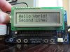
I also found the data sheet for the controllers:

SPLC80D
https://www.electro-tech-online.com/custompdfs/2011/10/SPLC780D.pdf
(Timing info for 4-bit operation on pg. 11)

ST7066U:
https://www.electro-tech-online.com/custompdfs/2011/10/ST7066U.pdf
(pg. 25/42 shows more timing information for 4-bit operation mode)

___________________________

@Angry Badger - I managed to modify your 4-bit character input example. The difference is that I am using portD instead of C. The black bars across the first row now turns into 2 rows of light gray after about a half a second (So, the LCD was initialized? I don't see a black square in the first row or anything that your pictures indicate). However, the character commands do not work. No matter what I send in, the squares remain blank.

Here is the modified code I used:
Code:
//turns watch dog timer off, turn low voltage programming off, MCLR off need for +5V
#pragma config WDT=OFF, LVP=OFF, DEBUG=ON, MCLRE = OFF

//Internal oscillator, port function on RA6, EC used by USB 
#pragma config FOSC = INTOSCIO_EC 
#include <p18f4550.h>
#include <delays.h>

//Power LED (PortA)
#define LEDPin LATAbits.LATA0 //Define LEDPin as PORT D Pin 1

//LCD_RS: 0 = select instruction register, 1 = select data register
#define LCD_RS          LATDbits.LATD4      // RS = Register Select [lcd pin 04] pic pin 15
#define LCD_RW          LATDbits.LATD5      // RW = Read / Write [lcd pin 05] pic pin 16
#define LCD_En          LATDbits.LATD6      // En = Enable [lcd pin 06] pic pin 17
#define LCD_BF          PORTDbits.RD3       // BF = Busy Flag [pic pin 14]
#define LCDdata2port    LATD

void LCD_init (void);                       // subroutine for initialising lcd
void LCD_E (void);                          // subroutine for toggling lcd enable pin
void LCD_busy (void);                       // subroutine for reading lcd busy flag
void write2LCD (void);                      // subroutine for sending data to lcd
void LCD_char(void);                        // subroutine sets lcd RS pin and calls 'write to lcd' routine
void delay_250mS (void);                    // subroutine for 0.25s second delay

unsigned char data2LCD;                     // 8 bit variable
unsigned char RS_flag;                      // 8 bit variable


//+++++++++++++++++++++++++++++++++++++++++++++++++++++++++++++++++++++++++++++++++++++++++++++++
#pragma code
void main (void)
{

	TRISA = 0x00;
    ADCON1 = 0xF;                       // sets all analog channels as digital inputs

    TRISDbits.TRISD0 = 0;               // PORTD bit 0 (LCD pin11 [DB4])
    TRISDbits.TRISD1 = 0;               // PORTD bit 1 (LCD pin12 [DB5])
    TRISDbits.TRISD2 = 0;               // PORTD bit 2 (LCD pin13 [DB6])
    TRISDbits.TRISD3 = 0;               // PORTD bit 3 (LCD pin14 [DB7])
    TRISDbits.TRISD4 = 0;               // PORTD bit 4 (LCD pin4 [RS])
    TRISDbits.TRISD5 = 0;               // PORTD bit 5 (LCD pin5 [RW])
    TRISDbits.TRISD6 = 0;               // PORTD bit 6 (LCD pin6 [E])
    TRISDbits.TRISD7 = 0;               // PORTD bit 7
	
	LEDPin=1;	

    LATD = 0;
    PORTD = 0;
    LCD_RS = 0;
    LCD_RW = 0;
    LCD_En = 0;
    RS_flag = 0;
    data2LCD = 0;

    LCD_init();                         //call initialise lcd routine

//+++++++++++++++++++++++++++++++++++++++++++++++++++++++++++++++++++++++++++++++++++++++++++++++

    while(1)                            // main program 'start'
    {

    data2LCD = 'p';                     // 0b01001000;
    LCD_char();                         // display it on lcd
    delay_250mS();

    data2LCD = 'i';                     // 0b01100101;
    LCD_char();
    delay_250mS();

    data2LCD = 'c';                     // 0b01101100;
    LCD_char();
    delay_250mS();


    while (!LCD_En);                    // stop and wait here - everything is done

    }
}

void LCD_char (void)
{
    RS_flag = 1;                        // memory flag (set for writing to data register)
    write2LCD();                        // send data or instruction to lcd
    RS_flag = 0;
}
// ***** Start of LCD initialization *****


void LCD_init (void)

{   // See the HD47780 or ST7066 data sheets
    //8 bit_mode;
    //start software reset.


    Delay10KTCYx(3);                    // wait MINIMUM 15mS - allow Vcc to settle

    LCDdata2port = 0b00000011;          // put the data on portC
    LCD_E();
    Delay1KTCYx(2);                     // wait 4mS as per data sheet (4.1mS says data sheet)

    LCDdata2port = 0b00000011;
    LCD_E();
    Delay10TCYx(3);                    // wait 100uS as per data sheet

    LCDdata2port = 0b00000011;          // data sheet bit hazy as to when exactly
    LCD_E();                            // 'busy' flag can be read
    LCD_busy();

    LCDdata2port = 0b00000010;          // can wait for busy flag from here
    LCD_E();
    LCD_busy();

    // end of software reset


    // 4 bit mode from here

    // (1) function set

    // Data Length = 4 bits, 2 (or 4) line display, 5x8 font
    //
    data2LCD = 0b00101000;
    write2LCD();

    //(2) display on/off control
    // turn on display, no cursor and no cursor flash
    //
    data2LCD = 0b00001100;
    write2LCD();

    // (3) clear display
    //
    data2LCD = 0b00000001;
    write2LCD();

    // (4) entry mode set
    //  cursor moves to right
    //
    data2LCD = 0b00000110;
    write2LCD();

}
// ********* end of LCD initialization **********

void delay_250mS (void)
{
    Delay10KTCYx(6.25);                               // wait 0.25S

}
void write2LCD (void)
{
    LCDdata2port = ((data2LCD >> 4) & 0xf);         // swap nyybles, clear upper nyyble on port
    if (RS_flag)                                    // set indicates reading / writing data, not 'instructions'
        LCD_RS = 1;                                 // set RS
    LCD_E();                                        // latch data into lcd

    LCDdata2port = ((data2LCD) & 0xf);
    if (RS_flag)
        LCD_RS = 1;                                 // set RS again - was cleared when 'data2LCD' ANDED
    LCD_E();                                        // latch data into lcd
    LCD_busy();                                     // check busy flag after second four bit write.
}

void LCD_E (void)                                   // toggle the lcd enable bit

{
    LCD_En = 1;
    LCD_En = 0;                                     // data read into lcd on high to low transition of E

}

void LCD_busy (void)                                // read lcd 'busy' flag
{
    LCD_RS = 0;                                     // cannot read the busy flag if RS = 1!
    TRISDbits.TRISD3 = 1;                           // When TRIS = 0 it's DB7, Tris = 1 it's lcd busy flag.
    LCD_RW = 1;
    LCD_En = 1;
    while (LCD_BF);                                 // wait until 'busy' flag clear
    LCD_En = 0;
    LCD_RW = 0;
    TRISDbits.TRISD3 = 0;

}

If I can't get this to work could you guys maybe recommend a 2x16 LCD that you have used before so that it is easier to assist me? I would really appreciate it. Thanks.
 
Last edited:
I'm a little confused. In your first post you show the data pins connected to port B but in your later code you write to port D!

Can you confirm what is connected to where and post your latest code?

Mike.
 
I'm sorry for the confusion. I was trying out the other users code which required all of the LCD inputs to be on one port so I moved them over to port D. As a result the current connections are as follows:

E --> RD6
R_W --> RD5
RS --> RD4
DB7 --> RD3
DB6 --> RD2
DB5 --> RD1
DB4 --> RD0

I had V0 going to ground before, and now I have a 10k potentiometer going to it (Both produce dark enough boxes).

Latest code (following nehaven data sheet):

Code:
//turns watch dog timer off, turn low voltage programming off
#pragma config WDT=OFF, LVP=OFF, DEBUG=ON, MCLRE = OFF

//Internal oscillator, port function on RA6, EC used by USB 
#pragma config FOSC = INTOSCIO_EC 
#include <p18f4550.h>
#include <delays.h>

//Power LED (PortA)
#define LEDPin LATAbits.LATA0 //Define LEDPin as PORT D Pin 1

//LCD (Port B and 1 pin PortD)
#define  E	 LATDbits.LATD6 //Define LCD pinout E
#define  R_W LATDbits.LATD5 //Define LCD pinout R/W
#define  RS  LATDbits.LATD4 //Define LCD pinout RS
#define  DB7 LATDbits.LATD3 //Define LCD pinout DB7
#define  DB6 LATDbits.LATD2 //Define LCD pinout DB6
#define  DB5 LATDbits.LATD1 //Define LCD pinout DB5
#define  DB4 LATDbits.LATD0 //Define LCD pinout DB4


void command(char);
void write(char);
void Nybble(void);
void init(void);

void main()
{
	while(!OSCCONbits.IOFS);      //wait for osc stable
   	ADCON1 = 0x0F;                //make RA0 digital
  
    //data direction registers all 0's mean that all pins are set to output
	//all 1's means that all of the pins are set to operate as inputs
	TRISA = 0x00;  
	TRISB = 0x00; 
	TRISD = 0x00;
	while(1)
	{
		LEDPin=1;
		init();
		break;
	}
}

/**********************************************************/
//4-bit methods for LCD
/**********************************************************/
void command(char i)
{
//	P1 = i; //put data on output Port
//	D_I =0; //D/I=LOW : send instruction
	RS =0;

	DB7 = ((i>>3)&'1');
	DB6 = ((i>>2)&'1'); 
	DB5 = ((i>>1)&'1');
	DB4 = i&'1';

	R_W =0;   //R/W=LOW : Write
	Nybble(); //Send lower 4 bits
	
	DB7 = ((i>>7)&'1');
	DB6 = ((i>>6)&'1'); 
	DB5 = ((i>>5)&'1');
	DB4 = ((i>>4)&'1');


	Nybble(); //Send upper 4 bits
}

void write(char i)
{
	Delay1KTCYx(1.25);  //must wait 5ms, busy flag not available (used 5ms)
	//P1 = i; //put data on output Port
	//D_I =1; //D/I=HIGH : send data
	RS= 1;
	DB7 = ((i>>7)&'1');
	DB6 = ((i>>6)&'1'); 
	DB5 = ((i>>5)&'1');
	DB4 = ((i>>4)&'1');

	R_W =0; //R/W=LOW : Write
	Nybble(); //Clock lower 4 bits

//	P1 = i; //put data on output Port
	DB7 = ((i>>3)&'1');
	DB6 = ((i>>2)&'1'); 
	DB5 = ((i>>1)&'1');
	DB4 = i&'1';

	Nybble(); //Clock upper 4 bits
}

/**********************************************************/
void Nybble(void)
{
	E = 1;
	Delay1TCY(); //enable pulse width >= 300ns (used 4uS)
	E = 0; //Clock enable: falling edge
}

/**********************************************************/
void init(void)
{
	//P1 = 0;
	//P3 = 0;
		DB7 = 0;
		DB6 = 0; 
		DB5 = 0;
		DB4 = 0;

	Delay1KTCYx(5); //Wait >15 msec after power is applied (used 20mS)
	//P1 = 0x30; //put 0x30 on the output port

	//command(0x30);
	
		DB7 = 0;
		DB6 = 0; 
		DB5 = 1;
		DB4 = 1;

	
	Delay1KTCYx(1.25);  //must wait 5ms, busy flag not available (used 5ms)
	Nybble(); 			//command 0x30 = Wake up
	Delay10TCYx(5); 	//must wait 160us, busy flag not available (used 160uS)
	Nybble(); 			//command 0x30 = Wake up #2
	Delay10TCYx(5); 	//must wait 160us, busy flag not available (used 160uS)
	Nybble(); 			//command 0x30 = Wake up #3
	Delay10TCYx(5); 	//can check busy flag now instead of delay
	//P1= 0x20; 		//put 0x20 on the output port

	//command(0x20);
		DB7 = 0;
		DB6 = 0; 
		DB5 = 1;
		DB4 = 0;

	Nybble(); //Function set: 4-bit interface
	command(0x28); //Function set: 4-bit/2-line
	command(0x10); //Set cursor
	command(0x0F); //Display ON; Blinking cursor
	command(0x06); //Entry Mode set
}
/**********************************************************/
//End methods for LCD
/**********************************************************/

Also, in case anyone is confused the following lines are used to just shift and mask the upper and lower nibbles ( I tried playing with the order of lower and upper nibble I feed in first, but it doesn't seem to affect it):

Code:
       ...
       //Shift and mask upper nibble bits and send them out the corresponding pins
        DB7 = ((i>>7)&'1');
	DB6 = ((i>>6)&'1'); 
	DB5 = ((i>>5)&'1');
	DB4 = ((i>>4)&'1');
        ...
        //Shift and mask lower nibble bits and send them out the corresponding pins
	DB7 = ((i>>3)&'1');
	DB6 = ((i>>2)&'1'); 
	DB5 = ((i>>1)&'1');
	DB4 = i&'1';
I believe the default frequency of oscillation is 1MHz. I have tested this using the following code with the LED I have connected:

Code:
#define LEDPin LATAbits.LATA0 //Define LEDPin as PORT A Pin 1
...
while(1)
{
     //Delay 250K cycles (1 second at 1MHz since each instruction takes 4 cycles)
     Delay10KTCYx(25);
     LEDPin = ~LEDPin; //constantly inverts output
}
...
 
Last edited:
The write sequence of the nibbles is high nibble first. You have it the wrong way around in your command function. You also don't have a delay in your command function. After a command write you should wait at least 2mS, for data it only needs to be 50uS.

The other big error I spotted was the lines,
Code:
    DB7 = ((i>>7)&'1');
This is wrong as it will AND the bit with the ascii for 1 which is 0x31. Whilst it will actually work, it is a bad way to do things. So, simply change those lines to,
Code:
    DB7 = ((i>>7) & 1);


Or, you could make your Nybble routine take data,
Code:
#define LCDdata LATD

void Nybble(unsigned char dat)
{
    dat &= 0x0f;             //clear top bits of dat
    LCDdata &= 0xf0;         //clear bottom bits of port
    LCDdata |= dat;          //or the two and store at port
    E = 1;
    Delay1TCY();             //enable pulse width >= 300ns (used 4uS)
    E = 0;                   //Clock enable: falling edge
}

And now your Command routine can be,
Code:
void command(char i)
{
	RS =0;
	R_W =0;          //R/W=LOW : Write
	Nybble(i>>4);    //Send upper 4 bits
	Nybble(i);       //Send lower 4 bits
	Delay1KTCYx(2);  //must wait 2mS
}

You will of course have to change your init routine and note that to write 0x30 (wakeup) you will simply do Nybble(0x03).

Mike.
 
Last edited:
Thank you Pommie for the helpful response. I modified my code to include your simple yet more elegant solution, and I will keep in mind to use 1 instead of '1' when masking individual bits. However, I still see a black row of squares. The only difference is that I now see a blinking cursor (as the bottom of the init function indicates) right before the top row turns into black squares (so I think we are on the right track).

Here is my latest code with your revisions:

Code:
//turns watch dog timer off, turn low voltage programming off
#pragma config WDT=OFF, LVP=OFF, DEBUG=ON, MCLRE = OFF
 
//Internal oscillator, port function on RA6, EC used by USB 
#pragma config FOSC = INTOSCIO_EC 
#include <p18f4550.h>
#include <delays.h>
 
//Power LED (PortA)
#define LEDPin LATAbits.LATA0 //Define LEDPin as PORT A Pin 1
 
//LCD (PortD)
#define  E LATDbits.LATD6
#define  R_W LATDbits.LATD5 
#define  RS  LATDbits.LATD4
#define LCDdata LATD
 
 
void command(unsigned char);
void write(unsigned char);
void Nybble(unsigned char);
void init(void);
 
void main()
{
	while(!OSCCONbits.IOFS);      //wait for osc stable
   	ADCON1 = 0x0F;                //make RA0 digital
 
    //data direction registers all 0's mean that all pins are set to output
	//all 1's means that all of the pins are set to operate as inputs
	TRISA = 0x00;  
	TRISB = 0x00; 
	TRISD = 0x00;
	while(1)
	{
		LEDPin=1;
		init();
		break;
	}
}
 
/**********************************************************/
//4-bit methods for LCD
/**********************************************************/
void command(unsigned char i)
{
	RS =0;
	R_W =0;          //R/W=LOW : Write
	Nybble(i>>4);    //Send upper 4 bits
	Nybble(i);       //Send lower 4 bits
	Delay1KTCYx(2);  //must wait at least 2mS (2*1000*4/1e6 = 8ms used)
}
 
void write(unsigned char i)
{
	RS =0;
	R_W =0;          //R/W=LOW : Write
	Nybble(i>>4);    //Send upper 4 bits
	Nybble(i);       //Send lower 4 bits
	Delay1KTCYx(2);  //must wait 2mS
}
 
/**********************************************************/
void Nybble(unsigned char dat)
{
    dat &= 0x0f;             //clear top bits of dat
    LCDdata &= 0xf0;         //clear bottom bits of port (interested only in DB7-DB4)
    LCDdata |= dat;          //or the two and store at port
    E = 1;
    Delay1TCY();             //enable pulse width >= 300ns (used 4uS)
    E = 0;                   //Clock enable: falling edge
}
 
/**********************************************************/
void init(void)
{
	LCDdata=0x00;
 
	Delay1KTCYx(5); //Wait >15 msec after power is applied (used 20mS)
	//P1 = 0x30; //put 0x30 on the output port  
 
	Delay1KTCYx(1.25);  //must wait 5ms, busy flag not available (used 5ms)
	Nybble(0x30); 	       //command 0x30 = Wake up
	Delay10TCYx(5);        //must wait 160us, busy flag not available (used 160uS)
	Nybble(0x30); 	       //command 0x30 = Wake up #2
	Delay10TCYx(5); 	//must wait 160us, busy flag not available (used 160uS)
	Nybble(0x30); 	        //command 0x30 = Wake up #3
	Delay10TCYx(5); 	//can check busy flag now instead of delay

	//P1= 0x20; 		//put 0x20 on the output port

	Nybble(0x20); //Function set: 4-bit interface
	command(0x28); //Function set: 4-bit/2-line
	command(0x10); //Set cursor
	command(0x0F); //Display ON; Blinking cursor
	command(0x06); //Entry Mode set
	
	
}
/**********************************************************/
//End methods for LCD
/**********************************************************/

Should I use some commands to clear the screen ( I believe 0x01 clears the screen)? Maybe the initialization routine is missing some commands?

EDIT1:
_________

I tried using clear screen and changing Display command from 0x0F to 0x0B, but it didn't work. I still get a row of black squares after about a second of applying power.

Code:
//Bottom of initialization function
        Nybble(0x20); //Function set: 4-bit interface
	command(0x28); //Function set: 4-bit/2-line
	command(0x10); //Set cursor
	command(0x0B); //Display ON (Changed from 0x0F to 0x0B)
	command(0x01); //Clear Display (Added)
	command(0x06); //Entry Mode set

I also tried switching the nibble statements like you suggest above: nybble(0x03) and nybble(0x02) instead of 0x30 and 0x20

EDIT2:
_________

I adjusted the contrast so that the black boxes are barely visible and now I can see a blinking cursor fly by the screen. However, I still only see one row, and I am not sure if I can write a character to the display since I tried the line "write(0x30);" in main, which should put the number zero on the screen.

Here is a video showing how I adjusted the pot and what I currently see displayed on the character LCD:

https://www.youtube.com/watch?v=8OKNH_HdXA0
 
Last edited:
This has been bugging me and so I dug out my Unicorn board, put a 2*16 LCD on it and got it working.

I had to change the init routine and the write (RS=1). Plus I added a PutMessage routine.

Here's the result,
lcd-jpg.57464

Code:
//turns watch dog timer off, turn low voltage programming off
#pragma config WDT=OFF, LVP=OFF, DEBUG=ON, MCLRE = OFF
 
//Internal oscillator, port function on RA6, EC used by USB 
#pragma config FOSC = INTOSCIO_EC 
#include <p18f4550.h>
#include <delays.h>
 
//Power LED (PortA)
#define LEDPin LATAbits.LATA0 //Define LEDPin as PORT A Pin 1
 
//LCD (PortD)
#define  E LATDbits.LATD6
#define  R_W LATDbits.LATD5 
#define  RS  LATDbits.LATD4
#define LCDdata LATD
 
 
void command(unsigned char);
void write(unsigned char);
void Nybble(unsigned char);
void init(void);
void PutMessage(rom char *);

void main()
{
	while(!OSCCONbits.IOFS);      //wait for osc stable
   	ADCON1 = 0x0F;                //make RA0 digital
 
    //data direction registers all 0's mean that all pins are set to output
	//all 1's means that all of the pins are set to operate as inputs
	TRISA = 0x00;  
	TRISB = 0x00; 
	TRISD = 0x00;
        init();
        PutMessage("Hello World!");
        command(0xc0);
        PutMessage("Second Line.");
        while(1);
}
 
//Write a string to the LCD
void PutMessage(rom char *Message){
rom char *Pos = Message;
	while(*Pos!=0)
	    write(*Pos++);
}
 
/**********************************************************/
//4-bit methods for LCD
/**********************************************************/
void command(unsigned char i)
{
	RS =0;
	R_W =0;          //R/W=LOW : Write
	Nybble(i>>4);    //Send upper 4 bits
	Nybble(i);       //Send lower 4 bits
	Delay1KTCYx(2);  //must wait at least 2mS (2*1000*4/1e6 = 8ms used)
}
 
void write(unsigned char i)
{
	RS =1;
	R_W =0;          //R/W=LOW : Write
	Nybble(i>>4);    //Send upper 4 bits
	Nybble(i);       //Send lower 4 bits
	Delay1KTCYx(2);  //must wait 2mS
}
 
/**********************************************************/
void Nybble(unsigned char dat)
{
    dat &= 0x0f;             //clear top bits of dat
    LCDdata &= 0xf0;         //clear bottom bits of port (interested only in DB7-DB4)
    LCDdata |= dat;          //or the two and store at port
    E = 1;
    Delay1TCY();             //enable pulse width >= 300ns (used 4uS)
    E = 0;                   //Clock enable: falling edge
}
 
/**********************************************************/
void init(void)
{
    LCDdata=0x00; 
    Delay1KTCYx(15);    //Wait >15 msec after power is applied (used 20mS)
    Nybble(0x3); 	//command 0x30 = Wake up
    Delay1KTCYx(5);     //must wait 160us, busy flag not available (used 160uS)
    Nybble(0x3); 	//command 0x30 = Wake up #2
    Delay1KTCYx(5); 	//must wait 160us, busy flag not available (used 160uS) 
	
    command(0x20);      //Function set: 4-bit/2-line
    command(0x2c);      //Function set: 4-bit/2-line
    command(0x10);      //Set cursor
    command(0x01);      //Clear Display (Added)
    command(0x06);      //Entry Mode set
    command(0x0c);
}
/**********************************************************/
//End methods for LCD
/**********************************************************/
Let me know if this works or not.

Mike.
 

Attachments

  • LCD.jpg
    LCD.jpg
    128.5 KB · Views: 2,500
Last edited:
hey micro 9000
Code:
while(1)
	{
		LEDPin=1;
		init();
		break;
	}
in the main loop, there is nothing that redirects you to the display routine.. i think that is the problem.. :)
 
@Pommie Thank you so much for your help, but there is still a problem. The newer bit of code that you added does appear to properly initialize the LCD, but I only see a blinking cursor. The only thing I modified was changing "Hello World! Second Line" to just "Hello world."

Code:
init();
        PutMessage("Hello");
        command(0xc0);
        PutMessage("World");

Here is a video demonstrating the problem.

https://www.youtube.com/watch?v=60lzKOm9_20

Even more perplexing is that if I remove the "put messages" or I change them in anyway the blinking cursor in the video is no longer be displayed. I'm guessing that it was just luck that I put in the correct amount of characters for the display to output that blinking cursor that is present in the video. However, I now see two rows of boxes instead of just a single row.

@magnatro Yeah, I didn't call to the display routine since I just wanted to see a blink cursor so I could tell if the LCD initialized correctly. I'm not sure if there is a requirement to call the write or command routine in order to see what I have shown in the video.
 
Last edited:
Again, I thank you for taking the time and for your assistance. The code is the same. The only line I changed is in main where the put messages reside.

Code:
//turns watch dog timer off, turn low voltage programming off
#pragma config WDT=OFF, LVP=OFF, DEBUG=ON, MCLRE = OFF
 
//Internal oscillator, port function on RA6, EC used by USB 
#pragma config FOSC = INTOSCIO_EC 
#include <p18f4550.h>
#include <delays.h>
 
//Power LED (PortA)
#define LEDPin LATAbits.LATA0 //Define LEDPin as PORT A Pin 1
 
//LCD (PortD)
#define  E LATDbits.LATD6
#define  R_W LATDbits.LATD5 
#define  RS  LATDbits.LATD4
#define LCDdata LATD
 
 
void command(unsigned char);
void write(unsigned char);
void Nybble(unsigned char);
void init(void);
void PutMessage(rom char *);
 
void main()
{
	while(!OSCCONbits.IOFS);      //wait for osc stable
   	ADCON1 = 0x0F;                //make RA0 digital
 
    //data direction registers all 0's mean that all pins are set to output
	//all 1's means that all of the pins are set to operate as inputs
	TRISA = 0x00;  
	TRISB = 0x00; 
	TRISD = 0x00;
        init();
        PutMessage("Hello");
        command(0xc0);
        PutMessage("World");
        while(1);
}
 
//Write a string to the LCD
void PutMessage(rom char *Message){
rom char *Pos = Message;
	while(*Pos!=0)
	    write(*Pos++);
}
 
/**********************************************************/
//4-bit methods for LCD
/**********************************************************/
void command(unsigned char i)
{
	RS =0;
	R_W =0;          //R/W=LOW : Write
	Nybble(i>>4);    //Send upper 4 bits
	Nybble(i);       //Send lower 4 bits
	Delay1KTCYx(2);  //must wait at least 2mS (2*1000*4/1e6 = 8ms used)
}
 
void write(unsigned char i)
{
	RS =1;
	R_W =0;          //R/W=LOW : Write
	Nybble(i>>4);    //Send upper 4 bits
	Nybble(i);       //Send lower 4 bits
	Delay1KTCYx(2);  //must wait 2mS
}
 
/**********************************************************/
void Nybble(unsigned char dat)
{
    dat &= 0x0f;             //clear top bits of dat
    LCDdata &= 0xf0;         //clear bottom bits of port (interested only in DB7-DB4)
    LCDdata |= dat;          //or the two and store at port
    E = 1;
    Delay1TCY();             //enable pulse width >= 300ns (used 4uS)
    E = 0;                   //Clock enable: falling edge
}
 
/**********************************************************/
void init(void)
{
    LCDdata=0x00; 
    Delay1KTCYx(15);    //Wait >15 msec after power is applied (used 20mS)
    Nybble(0x3); 	//command 0x30 = Wake up
    Delay1KTCYx(5);     //must wait 160us, busy flag not available (used 160uS)
    Nybble(0x3); 	//command 0x30 = Wake up #2
    Delay1KTCYx(5); 	//must wait 160us, busy flag not available (used 160uS) 
 
    command(0x20);      //Function set: 4-bit/2-line
    command(0x2c);      //Function set: 4-bit/2-line
    command(0x10);      //Set cursor
    command(0x01);      //Clear Display (Added)
    command(0x06);      //Entry Mode set
    command(0x0c);
}
/**********************************************************/
//End methods for LCD
/**********************************************************/
 
Last edited:
I'm not sure what to suggest as that code works fine on my setup. Have you double checked your wiring?

Mike.
 
I'll double check it again and I'll try a few things with the code as well.

EDIT:
Wiring was incorrect. The way that the uC is oriented with the ribbon cables the wires were mixed up. It was a bit hard too see, but I had the data lines mixed up. I'm sorry for not checking more carefully. I'm going to test it out right now.

EDIT2: That did the trick thank you so very much. I'll post video in a sec.
 
Last edited:
Thank you everyone so much, I made a video to show a token of my appreciation:

https://www.youtube.com/watch?v=ZkrgRjbVZtQ

Here is the final code with the routine shown in the video:

Code:
//turns watch dog timer off, turn low voltage programming off
#pragma config WDT=OFF, LVP=OFF, DEBUG=ON, MCLRE = OFF
 
//Internal oscillator, port function on RA6, EC used by USB 
#pragma config FOSC = INTOSCIO_EC 
#include <p18f4550.h>
#include <delays.h>
 
//Power LED (PortA)
#define LEDPin LATAbits.LATA0 //Define LEDPin as PORT A Pin 1
 
//LCD (PortD)
#define  E LATDbits.LATD6
#define  R_W LATDbits.LATD5 
#define  RS  LATDbits.LATD4
#define LCDdata LATD
 
 
void command(unsigned char);
void write(unsigned char);
void Nybble(unsigned char);
void init(void);
void PutMessage(rom char *);
 
void main()
{
	while(!OSCCONbits.IOFS);      //wait for osc stable
   	ADCON1 = 0x0F;                //make RA0 digital
 
    //data direction registers all 0's mean that all pins are set to output
	//all 1's means that all of the pins are set to operate as inputs
	TRISA = 0x00;  
	TRISB = 0x00; 
	TRISD = 0x00;
        init();

		while(1)
		{
        	PutMessage("Thanks");
        	command(0xc0);
        	PutMessage("Pommie");
			Delay10KTCYx(50);

			command(0x01);      //Clear Display (Added)
			
			PutMessage("Thank");
       		command(0xc0);
        	PutMessage("You");
			Delay10KTCYx(50);

			command(0x01);      //Clear Display (Added)
			PutMessage("Electro");
        	command(0xc0);
        	PutMessage("tech");
			Delay10KTCYx(50);
	
			command(0x01);      //Clear Display (Added)

			PutMessage("Forum");
        	command(0xc0);
        	PutMessage("members");
			Delay10KTCYx(50);

			command(0x01);      //Clear Display (Added)
		}
        
}
 
//Write a string to the LCD
void PutMessage(rom char *Message){
rom char *Pos = Message;
	while(*Pos!=0)
	    write(*Pos++);
}
 
/**********************************************************/
//4-bit methods for LCD
/**********************************************************/
void command(unsigned char i)
{
	RS =0;
	R_W =0;          //R/W=LOW : Write
	Nybble(i>>4);    //Send upper 4 bits
	Nybble(i);       //Send lower 4 bits
	Delay1KTCYx(2);  //must wait at least 2mS (2*1000*4/1e6 = 8ms used)
}
 
void write(unsigned char i)
{
	RS =1;
	R_W =0;          //R/W=LOW : Write
	Nybble(i>>4);    //Send upper 4 bits
	Nybble(i);       //Send lower 4 bits
	Delay1KTCYx(2);  //must wait 2mS
}
 
/**********************************************************/
void Nybble(unsigned char dat)
{
    dat &= 0x0f;             //clear top bits of dat
    LCDdata &= 0xf0;         //clear bottom bits of port (interested only in DB7-DB4)
    LCDdata |= dat;          //or the two and store at port
    E = 1;
    Delay1TCY();             //enable pulse width >= 300ns (used 4uS)
    E = 0;                   //Clock enable: falling edge
}
 
/**********************************************************/
void init(void)
{
    LCDdata=0x00; 
    Delay1KTCYx(15);    //Wait >15 msec after power is applied (used 20mS)
    Nybble(0x3); 	//command 0x30 = Wake up
    Delay1KTCYx(5);     //must wait 160us, busy flag not available (used 160uS)
    Nybble(0x3); 	//command 0x30 = Wake up #2
    Delay1KTCYx(5); 	//must wait 160us, busy flag not available (used 160uS) 
 
    command(0x20);      //Function set: 4-bit/2-line
    command(0x2c);      //Function set: 4-bit/2-line
    command(0x10);      //Set cursor
    command(0x01);      //Clear Display (Added)
    command(0x06);      //Entry Mode set
    command(0x0c);
}
/**********************************************************/
//End methods for LCD
/**********************************************************/

Solved
 
Congratulations. Now you can have some fun with the rest of your project.

Mike.
 
HI Micro9900 , I have problem with this code I am using MPLAB IDE V8.8 this is code is debagieng fine with using MPLAB but when i sent to simulation with software proteus the micro-controller pic18f4550 not work also the LCD doesn't display anything I will attach the circuit to show u the connection thanks for helping me proteus circuit.png


this is the code :
#pragma config PLLDIV = 5
#pragma config USBDIV =2
#pragma config FOSC = HSPLL_HS

// In the next two lines, comment out either the fast clock or the slow clock

#pragma config CPUDIV = OSC1_PLL2 // Fast Clock
//#pragma config CPUDIV = OSC4_PLL6 // Slow Clock

#pragma config WDT = OFF, LVP = OFF

#include <p18f4550.h>
#include <delays.h>
#include <adc.h>
#include <xlcd.h>
#include <stdlib.h>

#define UPPER;
#define DATA_PORT PORTB ;
#define TRIS_DATA_PORT TRISB ;


#define RW_PIN PORTBbits.RB1; /* PORT for RW */
#define TRIS_RW DDRBbits.RB1 ; /* TRIS for RW */
#define RS_PIN PORTBbits.RB2; /* PORT for RS */
#define TRIS_RS DDRBbits.RB2; /* TRIS for RS */
#define E_PIN PORTBbits.RB0; /* PORT for E */
#define TRIS_E DDRBbits.RB0; /* TRIS for E */


void Delay_1msX (unsigned int miliseconds);
void Delay_100msX (unsigned int msec);
void SetCGRamAddr( unsigned char addr );
void ClearXLCD(void);
void SetCurXLCD(unsigned char data);
unsigned int i, t;
void main ()
{
//set I/O input output
TRISB = 0b00000000; //Configure PORTB I/O direction
//Configure PORTD I/O direction
PORTB = 0;

OpenXLCD( FOUR_BIT & LINES_5X7 );


WriteCmdXLCD(0x01); //Clear display

SetCGRamAddr(0x40); //Goto CGRAM address #1


// 90 Degree Rotated 'RH'
putcXLCD(0b11111);
putcXLCD(0b00100);
putcXLCD(0b11111);
putcXLCD(0b00000);
putcXLCD(0b01001);
putcXLCD(0b10101);
putcXLCD(0b10110);
putcXLCD(0b11111);

// 90 Degree Rotated '2T'
putcXLCD(0b10000);
putcXLCD(0b11111);
putcXLCD(0b10000);
putcXLCD(0b00000);
putcXLCD(0b01001);
putcXLCD(0b10101);
putcXLCD(0b10011);
putcXLCD(0b01001);

// Battery 1
putcXLCD(0b01110);
putcXLCD(0b11011);
putcXLCD(0b10001);
putcXLCD(0b10001);
putcXLCD(0b10001);
putcXLCD(0b10011);
putcXLCD(0b10111);
putcXLCD(0b11111);

// Battery 2
putcXLCD(0b01110);
putcXLCD(0b11011);
putcXLCD(0b10001);
putcXLCD(0b10001);
putcXLCD(0b10011);
putcXLCD(0b10111);
putcXLCD(0b11111);
putcXLCD(0b11111);

// Battery 3
putcXLCD(0b01110);
putcXLCD(0b11011);
putcXLCD(0b10001);
putcXLCD(0b10011);
putcXLCD(0b10111);
putcXLCD(0b11111);
putcXLCD(0b11111);
putcXLCD(0b11111);

// Battery 4
putcXLCD(0b01110);
putcXLCD(0b11011);
putcXLCD(0b10011);
putcXLCD(0b10111);
putcXLCD(0b11111);
putcXLCD(0b11111);
putcXLCD(0b11111);
putcXLCD(0b11111);

// Battery 5
putcXLCD(0b01110);
putcXLCD(0b11011);
putcXLCD(0b10111);
putcXLCD(0b11111);
putcXLCD(0b11111);
putcXLCD(0b11111);
putcXLCD(0b11111);
putcXLCD(0b11111);

// Battery 6
putcXLCD(0b01110);
putcXLCD(0b11111);
putcXLCD(0b11111);
putcXLCD(0b11111);
putcXLCD(0b11111);
putcXLCD(0b11111);
putcXLCD(0b11111);
putcXLCD(0b11111);

WriteCmdXLCD(0x01); //Clear display

SetCurXLCD(0); //Set cursor to line 1, position 0
putcXLCD(1); //Display user-defined graphic 1
SetCurXLCD(20); //Set cursor to line 2, position 0
putcXLCD(0); //Display user-defined graphic 0

SetCurXLCD(2); //Set cursor to line 1, position 2
for(i=2;i<8;i++) //Display user-defined graphic 2 to 7
{
putcXLCD(i);
}
putrsXLCD(" SK40C"); //Display "SK40C"

while(1) //Loop the battery level graphics
{
for(i=0;i<6;i++) //Refresh battery level graphics
{ //continuously every 500ms

SetCurXLCD(22); //Set cursor to line 2, position 2
putcXLCD(i+2); //Display current user-defined graphic
Delay_100msX(5); //Delay 500ms
}
}
}

void Delay_1msX (unsigned int miliseconds)
{
t=0;
while(t<miliseconds)
{
Delay1KTCYx(11);
Delay10TCYx(96);
Nop();
Nop();
Nop();
Nop();
Nop();
t++;
}
}

void Delay_100msX (unsigned int msec)
{
t=0;
while(t<msec)
{
Delay10KTCYx(119);
Delay1KTCYx(9);
Delay10TCYx(96);
t++;
}
}

void SetCurXLCD(unsigned char data)
{
if(data<16)
{
SetDDRamAddr(0x80+data);
}
else
{
data=data-20;
SetDDRamAddr(0xc0+data);
}
}
void DelayPORXLCD (void)
{
Delay1KTCYx(60);
return;
}

void DelayFor18TCY (void)
{

Nop();
Nop();
Nop();
Nop();

}
 
Status
Not open for further replies.

Latest threads

New Articles From Microcontroller Tips

Back
Top