Electro Tech is an online community (with over 170,000 members) who enjoy talking about and building electronic circuits, projects and gadgets. To participate you need to register. Registration is free. Click here to register now.
Welcome to our site! Electro Tech is an online community (with over 170,000 members) who enjoy talking about and building electronic circuits, projects and gadgets. To participate you need to register. Registration is free. Click here to register now.
hi,
A more efficient method would be to use a P Channel MOSFET, say a FDS6875, [in place of the TIP] this would reduce the voltage drop thats appearing across the TIP.
If you decide to use a MOSFET, I'll redo the circuit.
Whilst experimenting I figure that rather than a "hot" tip32 I will run a relay.
You helped me invert the signal to make the output switch off rather than on as in the original circuit.
As the device would have been on most of the time I didn't want to have a relay always energised but now it will only be energised for the shorter period.
Finding a suitable amperage relay was nigh impossible however this one **broken link removed** functions perfectly @ 45ma.
Changing to a reflective photo interrupter has meant a 50ma led circuit and a variable resistor on the emitter of <2k.
Sorry to be such a pain but You don't know how much I appreciate your assistance.
I too once was giving others assistance like you but no longer.
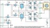
Using the above thumbnail circuit included in the post above (but with a common rail @ 5v and a single pole double throw relay instead of tip32) combined with the following circuit
I am going to switch this bi-polar stepper motor circuit
The stepper motor is 5 volt so will power all at 5 volt.
I want to switch off the motor by the opto interrupter and restart it by a momentary switch
I find that leaving the motor energised causes overheating whilst stationary (ie removing step/oscillator link)
Given that I are only able to access a single pole relay of suitable rating (1amp), where in circuit would it be best to switch off the motor supply and where would it be best to restart the circuit by using a 50ma switch
0.7MM SPST MICRO TACTILE SWITCH
- Rating: 12VDC 50mA
(**broken link removed**)
2/. Can I replace the mosfets with a transistor and diode? (Motor is 2.75-7.2vdc, 12 ohm, Current is .44 amp @ 3v .8 amp @ 5v, 1amp @ 6v)
3/. Where would be the best location to restart the motor after the photo interrupter has deactivated the relay bearing in mind using a 50ma tactile switch
a/. Across the photo interrupter output emitter collector, b/. across transistor BC337 c/. across the transistor 2N2222 d/. or where else and how
hi,
Ref the single pole relay, looking at the circuit there is no point in the circuit where a single pole 1amp contact relay could be used to switch off BOTH HBbriges.
The other point that you should consider, is if you switch off the +5V, the powered 'holding' torque of the motor will be lost and the 'load' that the motor shaft is driving could move from the set position.
There are P/N MOSFETs that will operate on a Vgs of about 2.5V, replacing the MOSFETs with transistors would mean a major change to the circuit.
On the web there are transistor HBridges also HBridge ic's.
1/.Would switching off the 12v+ supply to source of h bridge mosfets stop the mosfets or motor getting warm?
(The motor requires no holding torque.)
2/. Where would be the best location to restart the motor after the photo interrupter has deactivated the relay bearing in mind using a 50ma tactile switch
a/. Across the photo interrupter output emitter collector, b/. across transistor BC337 c/. across the transistor 2N2222 d/. or where else and how
1/.Would switching off the 12v+ supply to source of h bridge mosfets stop the mosfets or motor getting warm?
(The motor requires no holding torque.) It should do, if the full bridge is switched.
2/. Where would be the best location to restart the motor after the photo interrupter has deactivated the relay bearing in mind using a 50ma tactile switch
a/. Across the photo interrupter output emitter collector, b/. across transistor BC337 c/. across the transistor 2N2222 d/. or where else and how
This site uses cookies to help personalise content, tailor your experience and to keep you logged in if you register.
By continuing to use this site, you are consenting to our use of cookies.