I know very little about electronics even though I was an electrician once.
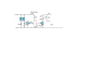
I have this little circuit as a train interrupter.
Silicon Chip Online - Circuit Notebook
I wish to change it to switch "off" when interrupted, to operate it on 5 volt, and preferably for the transistor to switch another 5 volt 1 amp positive circuit directly by a bigger transistor instead of by the relay.
A simple problem for any guru I'm sure.
I look forward to your reply
")
