Electro Tech is an online community (with over 170,000 members) who enjoy talking about and building electronic circuits, projects and gadgets. To participate you need to register. Registration is free. Click here to register now.
Welcome to our site! Electro Tech is an online community (with over 170,000 members) who enjoy talking about and building electronic circuits, projects and gadgets. To participate you need to register. Registration is free. Click here to register now.
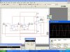
Thanks Hero. now Last thing is that, this attached circuit is using dual power supply. can you tell how can i use the same circuit with a single Power supply without affecting other parameters.?
Thanks
I would replace the three 741s with a TL084 which has four decent quality op-amps on one chip rather than using three separate poor quality op-amp ICs.
The fourth op-amp would be configured as a virtual earth. I would connect it as a non-inverting unity gain buffer with a potential divider set to half the supply voltage as the input and the output connected to all the 0V nodes in the original circuit. You will need to add an AC coupling capacitor to the output of the oscillator.
If you replace the 9V battery with 12V, you'll get a +6V and a -6V rail. connect the 0V to the 0V parts of your schematic and the + and - 6V to the positive and negative respectively. Obviously the output voltage will be halved.
Ordinary opamps cannot oscillate in your circuit at 200kHz.
The max frequency for a 741 opamp is 9kHz and the max frequency for a TL084 opamp is 100kHz.
In post #19 the OP thinks his oscillator can go from 1Hz to 200kHz.
"ok. now with this I've Completed my Phase shift Oscillator. which is for low Freqencies (i think from 1Hz to 200KHz)."
At 200kHz the max output of a 741 opamp is only 1.5V p-p and its gain is only 4.
Hey! i've read the datasheet of ordinary 741 Ic. it's Maximum out current is 20mA. that is not sufficient for my circuit. actually i have an A.c Motor.which Operates on 300Hz 220V. i have 220v aroung me in house Electricity but 50Hz. so i thought to Convert D.c 12v from a battery to A.c with 300Hz(which now i can do) then use a Transformer to step up the voltage and then i thought to supply the voltage to motor but the output 20mA from opAmp is not sufficient for this perpose. so i thought to find a more opwerful or an OpAmp which can give me Current more then 20mA. So i chose LM12 whose Maximum output Current is 10A. i thought it would be same as the ordinary 741 Opamp but it is not working at all in the same circuit i attached up. i just remove the non-inverting Amplifiers and used it intead of the main inverting Amplifier, but it is not working at all. what should i do.? is this LM12 is change from the 741 in working? i connected it as it is described in datasheet. help me thanks.
Please attach the schematic of the oscillator that does not work with an LM12.
Don't you know that the output voltage from an opamp is reduced when its output current is high?
An ordinary opamp has an output of 10V p-p when it has a 12V supply and no load which is 3.5V RMS.
When the opamp is loaded so its peak current is 20mA then its max output voltage is reduced to 3V p-p which is only 1.06V RMS.
Don't you know that when a transformer steps up voltage then it steps down current?
The power out of a transformer is a little less than the power into a transformer.
1V at 20mA into a transformer results in 300V at a little less than only 67uA at the output.
The LM12 is obsolete but there are plenty of similar audio amplifier ICs available.
An amplifier that has a 70V supply and a peak output current of 4A has an output voltage of 21.2V RMS and an output power of 56W RMS into 8 ohms. If you use a transformer to stepup the 21.2V to 300V then the peak current will be reduced to a little less than 283mA. The average current will be 200mA.
How much RMS current does the motor use at 300V? Or how much power?
Hello.
I Want to power an A.c motor whose Operating Specifications are:
165V
2.4A
300Hz
0.37w
these are the specifications written on the motor.
Now tell me how can i use my circuit to operate this Motor.?
Thanks
Sorry! Hero i did not understand your post. please make it clear. what to connect with whose output.? And please tell me what mean by gigantic audio Amplifier.? and also tell me How gigantic an amplifier can be? I've learnt Class A,B,AB and C Amplifiers. please give some idea in details. or it would be better if you give me a block diagram of the circuit.
thanks
what i understand is first convrt dc into ac with required frequncy and then put the signal into class D amplifier. can i take this amplifier directely to 165v 2.4 A?
Yes, that's it but class D amplifier is not easy to make and I doubt you'll be able to buy one that will run from 235VDC (the input voltage required for an RMS output voltage of 165VAC) off the shelf.
This site uses cookies to help personalise content, tailor your experience and to keep you logged in if you register.
By continuing to use this site, you are consenting to our use of cookies.