PG1995
Active Member
Thank you so much!
I think we are close to the end now and anything beyond this point is mathematical which I do tend to get into at some point later.
0 degrees (min) to 180 degrees (max); the mid point is 90 degrees (when input frequency is equal to VCO free-running frequency)
0 degrees (max) to -180 degrees (min), the mid point is -90 degrees
A PLL tries to make the frequencies equal and keep the phase difference between input frequency and output frequency either 90 degrees or -90 degrees in most cases, if not all. For example, suppose that a PLL is locked, and the frequency is in the middle or at mid point, which means input frequency is equal to free-running frequency of VCO and the phase difference will be 90 degrees assuming the range from 0 degrees to 180 degrees. If the input frequency is increased, the phase difference would increase, say by 40 degrees. It means the total phase difference is: inherent + introduced = 90 + 40 = 130 degrees. The phase comparator increases it voltage above mid point which in turn increases VCO frequency. After some time VCO frequency is same as that of input frequency and the phase difference is again 90 degrees. The output voltage would remain above the mid point value because otherwise VCO's frequency will decrease.
I hope I have it correct.
Question:
I think that what you are saying above could be related to something you said earlier; I've quoted it below at the bottom. The frequencies are not close enough; actually they are at the extremes. The phase detector output is not high or low for a long enough time that the VCO frequency can change enough to actually achieve phase lock. As you said, the phase detector output varies between minimum and maximum at around the difference between the mid frequency and the maximum lock frequency. But why is so that it varies between minimum and maximum at around the difference between the mid frequency and the maximum lock frequency?
Suppose that 90 kHz is mid frequency and maximum lock frequency is 120 kHz. The difference between mid frequency and lock frequency is 30 kHz.
It will vary between 60 kHz and 120 kHz.
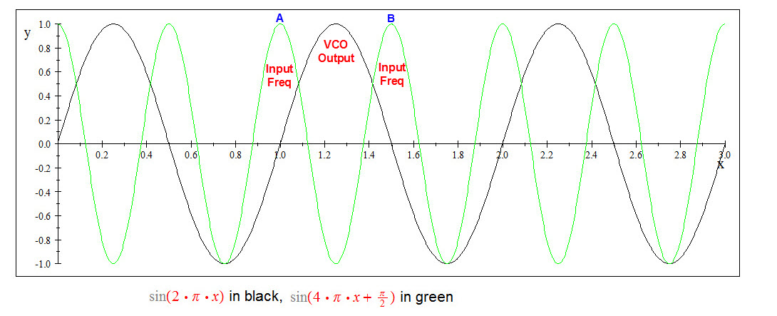
The picture below is just to convey a rough idea.
For point A the phase detector thinks that input frequency is less than that of VCO and starts decreasing the voltage below mid value but as it doing so the point B confuses phase detector to think that input frequency is more than that of VCO so it starts increasing the output voltage above mid value. This results into a varying voltage. Do I make sense?
I think we are close to the end now and anything beyond this point is mathematical which I do tend to get into at some point later.
A voltage multiplier, or an XOR gate can be used as a phase comparator, and they will often give a maximum output at 180 or at 0. The mid output will be at 90 degrees or -90 degrees and so that will be the design point.
0 degrees (min) to 180 degrees (max); the mid point is 90 degrees (when input frequency is equal to VCO free-running frequency)
0 degrees (max) to -180 degrees (min), the mid point is -90 degrees
A PLL tries to make the frequencies equal and keep the phase difference between input frequency and output frequency either 90 degrees or -90 degrees in most cases, if not all. For example, suppose that a PLL is locked, and the frequency is in the middle or at mid point, which means input frequency is equal to free-running frequency of VCO and the phase difference will be 90 degrees assuming the range from 0 degrees to 180 degrees. If the input frequency is increased, the phase difference would increase, say by 40 degrees. It means the total phase difference is: inherent + introduced = 90 + 40 = 130 degrees. The phase comparator increases it voltage above mid point which in turn increases VCO frequency. After some time VCO frequency is same as that of input frequency and the phase difference is again 90 degrees. The output voltage would remain above the mid point value because otherwise VCO's frequency will decrease.
I hope I have it correct.
Question:
Now turn off the reference frequency. The phase comparator produces a mid voltage and the VCO moves to the mid frequency. Now turn on the reference frequency again, as the maximum lock frequency. The phase comparator will start producing a sine-ish wave, varying between minimum and maximum at around the difference between the mid frequency and the maximum lock frequency.
Although the VCO frequency is changing, it never quite gets to the maximum lock frequency because the phase comparator output is never stable at the maximum voltage for any length of time, and any filtering at all will stop there being a lock.
The reference frequency needs to be reduced a bit, to give the phase comparator and VCO a bit of time, in the cycle of phase comparator output waveform, to get to the right frequency. When that is done, the top of the capture range has been found.
I think that what you are saying above could be related to something you said earlier; I've quoted it below at the bottom. The frequencies are not close enough; actually they are at the extremes. The phase detector output is not high or low for a long enough time that the VCO frequency can change enough to actually achieve phase lock. As you said, the phase detector output varies between minimum and maximum at around the difference between the mid frequency and the maximum lock frequency. But why is so that it varies between minimum and maximum at around the difference between the mid frequency and the maximum lock frequency?
Suppose that 90 kHz is mid frequency and maximum lock frequency is 120 kHz. The difference between mid frequency and lock frequency is 30 kHz.
It will vary between 60 kHz and 120 kHz.
The picture below is just to convey a rough idea.
For point A the phase detector thinks that input frequency is less than that of VCO and starts decreasing the voltage below mid value but as it doing so the point B confuses phase detector to think that input frequency is more than that of VCO so it starts increasing the output voltage above mid value. This results into a varying voltage. Do I make sense?
A phase locked loop relies on the frequencies being close enough that the phase detector output is high or low for a long enough time that the VCO frequency can change enough to actually achieve phase lock. It is very common to have a PLL where both the reference and the VCO frequencies are divided, to give enough time for a lock. If I have a 1 MHz reference, and a VCO that gives me 0.8 - 1.2 MHz, when the VCO is at maximum or minimum, the frequency difference is 200 kHz, so the phase comparator output will only be above zero for 2.5 microseconds, an the VCO might well not be able to respond that fast.
If both frequencies were divided by 1000, the phase comparator output will be high for 2.5 milliseconds.
