PG1995
Active Member
Hi,
Could you please help me to understand the operation of a closed lock loop as a frequency multiplier?
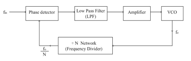
Source #2 says, "Since the output of frequency divider is locked to input frequency fin, the VCO is actually running at a multiple of the input frequency. The desired amount of multiplication can be obtained by selecting a proper ÷N network.
∴Input to phase detector, fin=fo/N
∴fo=Nfin".
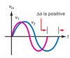
I don't follow how the output frequency becomes N*f_in when the phase detector is fed with the reference frequency f_in and feedback N*f_in. I understand that the output of the phase detector is a voltage proportional to the phase difference between the two inputs. The low pass filter attenuates high frequency content. I don't understand how the output of the VCO is at a frequency that is N times the input supplied to the frequency reference input.
Block diagram #1:
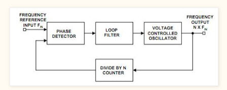
Source #1: https://electricalelctronic.blogspot.com/2012/02/phase-locked-loop-pll.html
Block diagram #2:
Source #2: https://www.electronics-tutorial.net/analog-integrated-circuits/phase-locked-loop/pll-applications/
Helpful links:
1: https://www.cardinalxtal.com/static/frontend/files/cardinal-phase-lock-loop-basics.pdf
2: https://www.sciencedirect.com/topics/engineering/phase-locked-loops
Could you please help me to understand the operation of a closed lock loop as a frequency multiplier?
Source #2 says, "Since the output of frequency divider is locked to input frequency fin, the VCO is actually running at a multiple of the input frequency. The desired amount of multiplication can be obtained by selecting a proper ÷N network.
∴Input to phase detector, fin=fo/N
∴fo=Nfin".
I don't follow how the output frequency becomes N*f_in when the phase detector is fed with the reference frequency f_in and feedback N*f_in. I understand that the output of the phase detector is a voltage proportional to the phase difference between the two inputs. The low pass filter attenuates high frequency content. I don't understand how the output of the VCO is at a frequency that is N times the input supplied to the frequency reference input.
Block diagram #1:
Source #1: https://electricalelctronic.blogspot.com/2012/02/phase-locked-loop-pll.html
Block diagram #2:
Source #2: https://www.electronics-tutorial.net/analog-integrated-circuits/phase-locked-loop/pll-applications/
Helpful links:
1: https://www.cardinalxtal.com/static/frontend/files/cardinal-phase-lock-loop-basics.pdf
2: https://www.sciencedirect.com/topics/engineering/phase-locked-loops