Continue to Site

Welcome to our site!

Electro Tech is an online community (with over 170,000 members) who enjoy talking about and building electronic circuits, projects and gadgets. To participate you need to register. Registration is free. Click here to register now.

  • Welcome to our site! Electro Tech is an online community (with over 170,000 members) who enjoy talking about and building electronic circuits, projects and gadgets. To participate you need to register. Registration is free. Click here to register now.

Phase lock loop shifted by 90 degrees - CD4046

Status
Not open for further replies.

MacIntoshCZ

Active Member
Hello there after a while =),
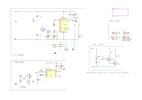
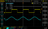
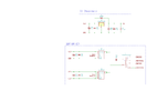
Blue trace is from DDS generator, its should simulate feedback from current transformer - tag: CT
Yellow trace is output from VCO.
I though phases will be same. Howeever current in coil is shifted by 90 degrees so i should no complain about that... I will use this for driving halfbridge.
Can someone explain why its shifted?
Thanks
 

Attachments

  • schematic-1.png
    schematic-1.png
    117.2 KB · Views: 251
  • schematic-2.png
    schematic-2.png
    67.2 KB · Views: 200
  • DS1Z_QuickPrint1.png
    DS1Z_QuickPrint1.png
    45.8 KB · Views: 223
It has a lot to do with which phase comparator you use and the way you develop the feedback signal. I agree the "edge lock" phase comparator II gives the most solid and stable lock but it is finicky with things like missing pulses.

Some versions of the CD4046 include a phase comparator III (an RS flip-flop) which can be used for adjustable phase.
 
The Phase Comparator I PC1 is an XOR frequency doubler, so you get 2f with near 50% duty cycle ideally with 90 deg phase shift to control the average voltage of the VCO. Since output is a tri-state switch this acts as an integrator with an RC filter. changing the duty cycle of the switch with the phase error. But all your pots and audio load pot affect the results and is very delicate tuning and not so great for production.

Component tolerances also affect the results.

Normally for a PLL design, you define your input frequency range over temp and voltage with nominal phase error and use an integrator with phase lead/lag compensation, but with a non-integrator or 1st order filter it is partial integration at AC but not at DC and proportional feedback. This allows missing pulses to be ignored. The input f range and input/output tracking jitter characteristics ought to be defined to make it track the way you want. ie. jitter reduction or maximum phase error etc. You can also use dual PC's and or dual BW with an analog switch for fast lock-in and slow tracking.

The Type II or PC2 is phase/frequency comparator but with more etc jitter noise.
 
Last edited:
if you need very tight quadrature 90 deg separation , a PLL is not how to do it.

You use a 4f signal then divider by 4 to get quadrature signals
 
Status
Not open for further replies.

Latest threads

New Articles From Microcontroller Tips

Back
Top