Continue to Site

Welcome to our site!

Electro Tech is an online community (with over 170,000 members) who enjoy talking about and building electronic circuits, projects and gadgets. To participate you need to register. Registration is free. Click here to register now.

  • Welcome to our site! Electro Tech is an online community (with over 170,000 members) who enjoy talking about and building electronic circuits, projects and gadgets. To participate you need to register. Registration is free. Click here to register now.

Phase between circuits.

Status
Not open for further replies.

alphadog

Banned
Hey.

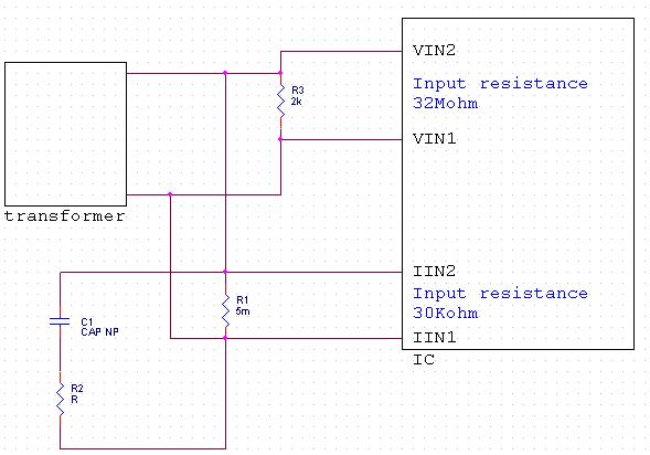
I have a chip which receives two pairs differentials inputs : (VIN1, VIN2) & (IIN1, IIN2).

I need to make a certain phase difference between the input voltage of (VIN1, VIN2) and the input voltage of (IIN1, IIN2).

I built this configuration and i wanted to ask if its ok.
(VIN1, VIN2) should get a pure sine wave, and (IIN1, IIN2) should get a sine wave which has phase in it.

The constraints are that R3 must be connected to (VIN1, VIN2) and R1 must be connected to (IIN1, IIN2).

What do you think?

Thanks.


pc-jpg.27640
 

Attachments

  • PC.JPG
    PC.JPG
    36.2 KB · Views: 254
Last edited:
Because i love to learn more and more.

This post is not about me but about circuits, you're welcome to ask me this question in another channel. :)
 
I assume your series RC circuit is what is the load current and voltage you are trying to measure.

1. You have a very low resistance in parallel with every other capacitor and resistor in your circuit. The equivelant resistance of parallel resistances is always lower than the lowest parallel resistance (resistances very low to other resistances in parallel connections will dominate the equivelant resistance. The more disparate the resistances are, the more the equivelant resistance approaches the parallel element of the lowest resistance). Your circuit will not work, whatever it's designed to do as is, with or without phase shifting. It is basically a 5mohm short-circuit.

2. You misunderstand how current sense resistors are supposed to be used. They must be connected in series with all load currents that they are measuring.

3. Why is the 2K resistor there? You are trying to measure voltage aren't you? Voltage is measured in parallel...to both the RC-load and the transformer which should all be in parallel with each other. No 2K resistor is needed and it will distort the measurements as it's value gets smaller relative to the RC-load impedance. Just measure the voltage directly across the RC load which should be the same as the voltage across the transformer output since they are in parallel.

4. Why do you want a phase shift? That defeats the purpose of a simultaneous current/voltage measurement.
 
Last edited:
Like this, but without phase shift becuase I still don't know why you need it and it would be difficult to add it in.

I am also assuming that the series-RC connection is your load.

I am also assuming it is a power load, not a signal laod because why would you care about the current measurement otherwise? Making it a power load also makes it much more difficult to add a phase shift.

I am also assuming your IC can accept the bipolar AC signals without damaging itself.

I am also assuming that you are trying to measure the current and the voltage of the RC series load.

Because seriously, you've told us very little. We appreciate the schematic...but it's not enough because it's only telling us HOW you are trying to do whatever you are trying to do, not WHAT you are actually trying to do.
 

Attachments

  • Schem.pdf
    6.7 KB · Views: 230
Last edited:
dknguyen you are the best!

I know that i gave little information and will remember to add mroe when i post a topic.

Thank you, you help me a lot. :)
 
Status
Not open for further replies.

Latest threads

New Articles From Microcontroller Tips

Back
Top