Continue to Site

Welcome to our site!

Electro Tech is an online community (with over 170,000 members) who enjoy talking about and building electronic circuits, projects and gadgets. To participate you need to register. Registration is free. Click here to register now.

  • Welcome to our site! Electro Tech is an online community (with over 170,000 members) who enjoy talking about and building electronic circuits, projects and gadgets. To participate you need to register. Registration is free. Click here to register now.

PCB schematic for 16 led 12 pattern pcb

Status
Not open for further replies.
Hello Everyone,
I need some help here. I am looking for schematic for a pcb to flash 16 leds in 12 different patterns.
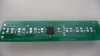
I need the pcb to be about 2 and 5/16 inches by 0.5 inches
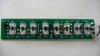
There would be 2 rows of 8 leds, with both rows flashing together
I make diecast model police cars with flashing leds and I would want to put the pcb into a light bar.
The patterns would be controlled by a tap switch and run off a 9 volt battery.
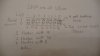
I will number the leds from left to right 1-8, both rows will flash at the same time, the leds will be paired up front and back.

Pattern 1- 1+2 and 7+8 flash at same time, than 3+4+5+6 flash at same time

Pattern 2- 8-1 flash from left to right, leds just flash from left to right all the time

Pattern 3- 1-8 flash from right to left, leds just flash from right to left and repeat the cycle, like pattern 2 but opposite

Pattern 4- 1 and 8 are still, 2+3+4 strobe flash, than 5+6+7 strobe flash

Pattern 5- 4 and 5 are still, 1+2+3 scan from left to right and right to left, while 8+7+6 scan from right to left and rleft to right, so 1 always flashes with 8, 2 with 7, and 3 with 6

Pattern 6- 3-6 are still, 1+2 flash than 7+8 flash, wigwag between 1+2 and 7+8

Pattern 7- 1,4,5,8 are still, 2+3 strobe than 6+7 strobe, wigwag strobe between 2+3 and 6+7

Pattern 8- 1-4 strobe than 5-8 strobe, wigwag strobe between 1-4 and 5-8

Pattern 9- 1-8 flash from left to right and than go back from right to left, scanning back and forth

Pattern 10- all odds flash at same time than all evens flash at same time, wig wag between all odds and all evens

Pattern 11- While 1+2 strobe 5+6 just flash, than 7+8 strobe, and 3+4 just flash

Pattern 12- 1 flashes in sequence from left to right to four and back in sequence to one, 8 flashes in sequence from right to left to 5 and then in sequence back to 8.

If possible can there be selectable speeds?

Thanks Everyone,Patrick
 
Sounds like a job for a pic...but I'm not into coding( takes me all my time to write my post code :) )


How big are the cars? just thinking about the size of the 9v battery..
 
Last edited:
Sounds like a job for a pic...but I'm not into coding( takes me all my time to write my post code :) )


How big are the cars? just thinking about the size of the 9v battery..

The Cars are 1/18 scale, they are about a foot long. The 9 volt is located in the trunk.
The light bars on the models are about 2 and 5/16 inches long by 0.5 inches wide.
 
I have several 1/18 WW2 tanks, planes etc. Nice scale but takes up lots of space.

If it's just one off you're best bet is to simply hand wire (point to point) as the cost of designing and developing a PCB (or you can DIY with Eagle CAD or Sprint Layout etc...)

Any microcontroller will give you the flexibility you desire.

Where would I start? I'm not really good with working with microcontrolers, don't really know much about them.
Thats why i'm asking for a schematic, or maybe someone could design a pcb that would work.
 
It's rare that another forum member will design something from schematic to layout & programming unless they have a similar need or use for such a device. We can point you in the right direction.

It is possible to drive 20 LEDs with a tiny 8pin PIC it's called charlieplexing and if you search the forums you'll find several topics on it.

The drawback to charlieplexing is each LED is only on for 1/( number of LEDs ) so you have to get some really bright LEDs for it to work, it's also tricky to program compared to simply driving one LED per pin.
 
I have a simple circuit using a PIC chip that does what you require:
 

Attachments

  • RC-car.gif
    RC-car.gif
    5.2 KB · Views: 2,357
I have a simple circuit using a PIC chip that does what you require:

Is this for only 8 leds though? I would need two rows of 8 leds, for a total of 16 leds. Would I have to program anything on the pic, or does your drawing include all the codes necessary to run the 12 patterns described.

Thanks,Patrick
 
There are 16 LEDs on the circuit diagram.

Oh ok I see it now. Are all the codes on the diagram for the 12 patterns?
Would this also come out to be 2 and 1/4 inches long by 0.5 inches wide?
Here is a quick drawing I put together.
 

Attachments

  • P1000835.JPG
    P1000835.JPG
    2.8 MB · Views: 1,314
So it's only 8 LEDs since the front & back are paired, that does make it simpler. A simple 4x2 mux would allow that and be fairly simple to program and could still use a tiny 8 pin PIC (4+1 for the mux, 1 for a pushbutton) with the current state pattern stored in EEPROM.
IMO the simplest language for a beginner is BASIC and MeLabs PICBASIC should fit the bill (not sure if you need standard or pro for the EEPROM)
As for PCB layout it's pretty straight forward, EagleCAD or Sprint Layout. The schematic is napkin simple.
First order of business is find a suitable LED, HE Reds are pretty bright but you might want blue, yellow etc... Also the size 3mm & 5mm are the most common, they make all sorts and shapes and it's worth a trip to the DigiKey Corp. | Electronic Components Distributor | United States Home Page or Mouser Electronics - Electronic Component Distributor site to look at what's available.

So take a look and get post your findings on the LED.

PS Colin's schematic will work fine (I missed it when I started posting)
 
Last edited:
IMO the simplest language for a beginner is BASIC and MeLabs PICBASIC should fit the bill (not sure if you need standard or pro for the EEPROM)

Why are you scaring people away by advising BASIC?
The PIC chip has only 35 instructions and you don't have to learn anything else.
You certainly don't have to use the EEPROM.

It a simple sub-routine for each effect while looking for a press of the button to go to the next sub-routine.
You certainly don't need anything complex like BASIC.

So I would have to learn these 35 instructions to program the pic right?
Could you give me a list off the instructions or a url to a website where I could learn about these? Once I program the pic I would just need to put together the PCB right?

I get my leds from here, https://www.modeltrainsoftware.com/bl-214f.html
but I call the store to get them unwired, not as listed
on the website where they are only wired.
 
Last edited:
Hi,

according to colin's suggested circuit here is a PCB layout.

Dimensions are: 2.0250X0.5inches

Except for the ON/OFF switch everything is on board.

PM me for the Eagle files.

Boncuk
 

Attachments

  • LED-BARS.jpg
    LED-BARS.jpg
    40.2 KB · Views: 1,060
  • LED-BARS-SILK.jpg
    LED-BARS-SILK.jpg
    35.6 KB · Views: 796
I finnaly found it!!!
I have been looking for this for weeks after I moved.
Here are pictures of what I am trying to get a layout/schematic for.
What Colin came up with was almost like it except for the leds wern't layed out across the whole board and the pic is on the bottom off the pcb.
Can someone help me get a layout/schematic for this?
Boncuk?
 

Attachments

  • P1000820.JPG
    P1000820.JPG
    2.8 MB · Views: 1,296
  • P1000825.JPG
    P1000825.JPG
    2.7 MB · Views: 895
Status
Not open for further replies.

Latest threads

New Articles From Microcontroller Tips

Back
Top