Continue to Site

Welcome to our site!

Electro Tech is an online community (with over 170,000 members) who enjoy talking about and building electronic circuits, projects and gadgets. To participate you need to register. Registration is free. Click here to register now.

  • Welcome to our site! Electro Tech is an online community (with over 170,000 members) who enjoy talking about and building electronic circuits, projects and gadgets. To participate you need to register. Registration is free. Click here to register now.

pcb malfunction

Status
Not open for further replies.

baristini

Member
Hi everyone!

I have a technics keyboard, that when we plug in the only thing it shows it the LCD ilumination.

I made a few measures on power and initial PCB and find every VR are working and power is getting in main PCB.

In this main PCB there is a 32 bit microcontroller MN103002A.

The issue is, how can i make sure this microcontroller is working? Shall i measure VSS and VDD voltages? What is the diference betwenn these 2 voltages ( VSS vs VDD )?

I send in attach block diagram of all circuits ( if anyone have time to watch.. lol ).

Thanks a lot for any help or hint!!
 

Attachments

  • IC04.MN103002A.PDF
    107.1 KB · Views: 266
  • diagramablc.jpg
    3.5 MB · Views: 200
VSS is the IC 0V, the circuits internal power "ground" or common.

VDD is the positive power to the IC, typically either 5V or 3.3V, though other voltages are possible.

Measuring those would show that the power supply to the IC is OK, but not that the IC itself is OK or running a program.
 
Do you have an oscilloscope?

If so, look for activity on the rd/wt, data and address pins. Also check that the RST pin (reset) goes low briefly when power is applied, then stays at high level (3.3v?)
 
Nice logic diagram...
IC4 RST on CN9 or CN102
 
Last edited:
Well, already measure Vdd and it is 3.3V stable.
RST when turn on and off the system gets always 0volt.
I measure with multimeter only....

I get the osciloscope only tomorrow and get other measure!!

Meanwhile, what method do you think is best to test all system? check power of all ics? check data on microcontoller?

Thanks a lot!!
 
Well i took a measure on RST with an oscioloscope and get 0v continuous.. turning on and off.... doesnt get high :(

In what pins can i can measure Read/Write data?

Any hint?
 
If the CPU /RST in signal on pin 141 is being held low, you need to trace where than comes from - the CPU cannot do anything if it is being held in reset.
 
If the CPU /RST in signal on pin 141 is being held low, you need to trace where than comes from - the CPU cannot do anything if it is being held in reset.
Classic example, it's VERY, VERY rare for a micro-controller/processor to die - it's almost always something external, and reset or clock issues are common problems. He needs a service manual really.
 
well i said it wront. measuring /RST on R4 and C13 i get 2.9volt!! so i think reset is holding the processor. this voltage remains all the time the power is on until powering off....

I have the service manual!! i send it in attach!

thank for yout precious help!
 

Attachments

  • technics_sx-kn6000_service_manual.pdf
    10.6 MB · Views: 264
well i said it wront. measuring /RST on R4 and C13 i get 2.9volt!! so i think reset is holding the processor.
The reset signal is active low - that's what the / or bar above it means.

If it is continuously high (after briefly staying low when power is first applied), the CPU is not being locked in reset and should be running.

Look for activity on the RD/WT pin?
Also the /RAS and /CAS pins? Those are all related to memory access or refresh, so should be showing some regular activity?
 
Measuring R18 ( RD/WT ) i found 3.3 for 2 seconds after power on and then 0volt fix.
when powering of it goes up (3.3v) momentarily and then shuts down.

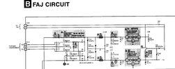
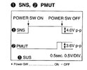
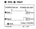
On the other hand, on service manual, there is a test to SNS signal.
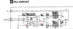
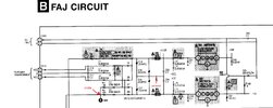
This is a test to the power pcb. I send the schematic of the power in in attach.

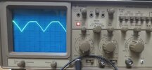
The the waveform i get on osciloscope is diferent from the one it is shownn in the manual...
I send images in attach.

thanks!
 

Attachments

  • 20231110_125103.jpg
    20231110_125103.jpg
    918.2 KB · Views: 234
  • Screenshot_20231110_140056_Dropbox.jpg
    Screenshot_20231110_140056_Dropbox.jpg
    195.2 KB · Views: 196
  • Screenshot_20231110_140122_Dropbox.jpg
    Screenshot_20231110_140122_Dropbox.jpg
    89.5 KB · Views: 220
But as we can see, the test point 1 to measure, the wave form should be flat.... or am i seeing wrong...
 

Attachments

  • Screenshot_20231110_140056_Dropbox.jpg
    Screenshot_20231110_140056_Dropbox.jpg
    192.5 KB · Views: 203
  • Screenshot_20231110_140122_Dropbox.jpg
    Screenshot_20231110_140122_Dropbox.jpg
    89.5 KB · Views: 200
But as we can see, the test point 1 to measure, the wave form should be flat.... or am i seeing wrong...
Try and find where it goes to, the waveform you're getting is what would be expected unless something (like a capacitor) is smoothing the signal - perhaps as a power ON / power OFF indication?. But nothing is shown on the section posted.
 
Status
Not open for further replies.

Latest threads

New Articles From Microcontroller Tips

Back
Top