Continue to Site

Welcome to our site!

Electro Tech is an online community (with over 170,000 members) who enjoy talking about and building electronic circuits, projects and gadgets. To participate you need to register. Registration is free. Click here to register now.

  • Welcome to our site! Electro Tech is an online community (with over 170,000 members) who enjoy talking about and building electronic circuits, projects and gadgets. To participate you need to register. Registration is free. Click here to register now.

PCB component identification (RF receiver?)

Status
Not open for further replies.

carlito77

New Member
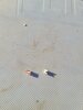
I am starting to learn more about electronics so I decided to take apart a Fluke 233 that would not power on after a (large) drop. I found that the components in the attached picture had come loose. It looks like they are adhesive backed rather than soldered..

When I took it apart it would not power on. One of these was still barely attached. It fell off when I was messing with it and after reassembly now it powers on but shows rf err (these meters have a detachable head and uses RF to detect if the head is present).. is that what these are? Or maybe even simple "reflectors" for lack of better word? Think at least one has a black dot on one side that I didn't catch in the pictures.

Thank you
 

Attachments

  • 20210722_183739.jpg
    20210722_183739.jpg
    1.6 MB · Views: 239
Very small picture, hard to tell what they are - but they do look like they have been ripped off the PCB (the LH one seems to have track remains on the bottom of it).

They look, as far as I can tell, more like a plug and socket than anything else.
 
Thank you for the response. I may need to pull it apart and get some pictures of the board; it doesn't seem to attach to anything other than the board physically; they are just sitting out in the open. And the spots on the PCB are a different color - copperish if I remember right. But maybe that's just a different material to help with adhesion rather than a conductive element
 
Thank you for the response. I may need to pull it apart and get some pictures of the board; it doesn't seem to attach to anything other than the board physically; they are just sitting out in the open. And the spots on the PCB are a different color - copperish if I remember right. But maybe that's just a different material to help with adhesion rather than a conductive element

The darker brown colour would be the adhesive where the track has pulled away.
 
I took things back apart and took some more pictures. Looks like it would have to be soldered in some way but I don't see a spot where it would conduct electricity unless that entire area on the PCB is conductive. Note that the solder mark on the top component is from my (very bad) attempt to reattach one of the white cubes to the board.
20210806_120849.jpg
20210806_120855.jpg
20210806_120921.jpg
20210806_121455.jpg
 
Those are a LED and a photo diode; they are from the two locations near the battery contacts.
They handle the "wireless" (presumably infra-red) optical communications between the meter body and display sections, to their opposite numbers in the other half.

The copper tracks from the PCB have ripped off and are still attached to the devices, hence nothing solderable where they were supposed to fit.

Both connections for Q204 are still clearly visible just above and below the damaged area, so that could be replaced by adding thin wires or foil to the device pads and soldering to the broken traces nearby.

I can only see the lower right connection from DS202 the left one seems to possibly go up under the battery terminal?
 
Status
Not open for further replies.

Latest threads

New Articles From Microcontroller Tips

Back
Top