Introduction
I am on with the conversion of an old Denford CNC milling machine from the 1980's electronics to be controlled by Mach3 from a PC.
Whilst all circuit boards can nowadays be bought off ebay to learn more about electronics I have decided to design") and build them myself. I have already done boards for step & direction of the axis and a board with 5-off relays to control stuff like coolant, spindle motor run, spindle direction etc.
and build them myself. I have already done boards for step & direction of the axis and a board with 5-off relays to control stuff like coolant, spindle motor run, spindle direction etc.
I am now building a circuit board for homing datums, overtravels, and spindle speed monitoring with optoisolation to protect the PC.
It will have seperate X, Y, Z homing inputs but a single overtravel input daisy-chained around the 6-off mechanical switches.
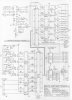
See attached drawing of planned circuit.
CN1 = 24v taken from 250mA supply off one of my drive cards.
CN6 = 5v taken from PC parallel port
CN8 = loop to X++, X--, Y++, Y--, Z++, Z-- overtravels
CN2, CN3, & CN4 = X, Y, & Z home switches which are 2 wire type Baluff proximity switches
CN5 = Spindle speed monitor which is also 2 wire Baluff proximity switch
CN7 = Inputs to Mach3 via parallel port
Circuits for X, Y, & Z home, and spindle speed are copied from original Denford drawings but modified to accept my 24v supply.
Condition
PC on, Mach3 running, parallel port cable connected, input ports assigned, 5V supply to CN6 present, 24v supply to CN1 present.
Mach3 set to display 'diagnostics' screen. Test circuit built on breadboard.
I have tested the circuit on a simulator progam and everything seems to works fine!
Problem
When only the overtravel loop is connected, the osilloscope shows a very clean switching of input pin on CN7 (pin1) from 0v when in safe working area, and a good 5V when Overtravel switch is thrown.
When only Z home is connected, osilloscope shows switching of input on CN7 (pin2) from 0v whilst in 'working area' and a good 5v when the Proximity switch is triggered when homed.
When I connect both Z home and Overtravels (haven't built breadboard with Y & X homes yet), and monitor on 2 channels of oscilloscope, both traces show 0v whilst in the safe working area, but when I move the Z axis towards home I only get 1v when the proximity switch is triggered until I continue moving the Z axis to trigger the Overtravel at which point both traces hit 5v. Obviously 1v isn't enough to trigger an input to Mach3, so what have I done wrong or need to do to fix it?
As I have plenty room on my standard 100mm x 160mm blank circuit boards i'd prefer to keep all these functions on the same board.
I would also prefer not to use another 5v ouput if that is the problem as I am running out of pins and I plan a 4th axis in future.
I could duplicate inputs and use the Overtravels as homes but that's admitting defeat and I ain't doing that, besides I am trying to learn and understand more.
Your guidance would be appreciated.
Thanks ...Achillies
I am on with the conversion of an old Denford CNC milling machine from the 1980's electronics to be controlled by Mach3 from a PC.
Whilst all circuit boards can nowadays be bought off ebay to learn more about electronics I have decided to design
and build them myself. I have already done boards for step & direction of the axis and a board with 5-off relays to control stuff like coolant, spindle motor run, spindle direction etc.I am now building a circuit board for homing datums, overtravels, and spindle speed monitoring with optoisolation to protect the PC.
It will have seperate X, Y, Z homing inputs but a single overtravel input daisy-chained around the 6-off mechanical switches.
See attached drawing of planned circuit.
CN1 = 24v taken from 250mA supply off one of my drive cards.
CN6 = 5v taken from PC parallel port
CN8 = loop to X++, X--, Y++, Y--, Z++, Z-- overtravels
CN2, CN3, & CN4 = X, Y, & Z home switches which are 2 wire type Baluff proximity switches
CN5 = Spindle speed monitor which is also 2 wire Baluff proximity switch
CN7 = Inputs to Mach3 via parallel port
Circuits for X, Y, & Z home, and spindle speed are copied from original Denford drawings but modified to accept my 24v supply.
Condition
PC on, Mach3 running, parallel port cable connected, input ports assigned, 5V supply to CN6 present, 24v supply to CN1 present.
Mach3 set to display 'diagnostics' screen. Test circuit built on breadboard.
I have tested the circuit on a simulator progam and everything seems to works fine!
Problem
When only the overtravel loop is connected, the osilloscope shows a very clean switching of input pin on CN7 (pin1) from 0v when in safe working area, and a good 5V when Overtravel switch is thrown.
When only Z home is connected, osilloscope shows switching of input on CN7 (pin2) from 0v whilst in 'working area' and a good 5v when the Proximity switch is triggered when homed.
When I connect both Z home and Overtravels (haven't built breadboard with Y & X homes yet), and monitor on 2 channels of oscilloscope, both traces show 0v whilst in the safe working area, but when I move the Z axis towards home I only get 1v when the proximity switch is triggered until I continue moving the Z axis to trigger the Overtravel at which point both traces hit 5v. Obviously 1v isn't enough to trigger an input to Mach3, so what have I done wrong or need to do to fix it?
As I have plenty room on my standard 100mm x 160mm blank circuit boards i'd prefer to keep all these functions on the same board.
I would also prefer not to use another 5v ouput if that is the problem as I am running out of pins and I plan a 4th axis in future.
I could duplicate inputs and use the Overtravels as homes but that's admitting defeat and I ain't doing that, besides I am trying to learn and understand more.
Your guidance would be appreciated.
Thanks ...Achillies