Electro Tech is an online community (with over 170,000 members) who enjoy talking about and building electronic circuits, projects and gadgets. To participate you need to register. Registration is free. Click here to register now.
Welcome to our site! Electro Tech is an online community (with over 170,000 members) who enjoy talking about and building electronic circuits, projects and gadgets. To participate you need to register. Registration is free. Click here to register now.
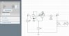
ctually i had to disconnect the load when the battery goes low which is monitored by a comparator which sends a high signal to the CTL pin of 4412, but when this happens the mosfet F2 diode conducted so to overcome that i used F1 in series,
can i use it like this ?? or can i just change the soucre and drain of F2 ??i have attached the schematic.
I m trying to build a circuit to cut the battery supply when the voltage is low.so initially i had only one mosfet F2 but the diode in it conducts even if gate is off , so the load draws current frm battery to over come that i connected the other mosfet...
or can i just reverse the drain and source of the mosfet ??
If the intrinsic diode of the P-channel mosfet is conducting from the V+ to the load and ground when the mosfet is off, you have the mosfet connected backward. With P-channel, the source goes to the positive supply.
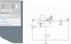
i did try using the online schematic editor and simulation using circuitlab.com ,when the battery supplied 9v and the gate s wer at 7v then only one mosfet on the left turned ON , the simulation result is shown on the left side of the attachment, the OUT node is zero even after the first mosfet is ON .In my design i use a p channel mosfet FDN306P, the symbol used in that editor is for P channel only.
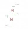
if i use a single p mosfet it would still conduct from drain to source if i connected drain to battery ,but if i connect battery to the source the direction of diode will be reversed and it will not conduct but when there is a voltage from the main supply the diode will be forward biased and will conduct and flow to battery ...am i correct ?
My Post #13 was written in response to your Post#11. I was writing while you were posting #12.
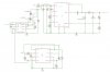
Simply put, if you look at the circuit in #12, why do you have M11 and its diode? (I am assuming you cannot find the proper symbol for this mosfet, so D7 and D8 were added to represent the intrinsic diodes.)
I get the feeling that there are some things in your design that are not shown in the schematic, like another power supply.
If you want to stop that hypothetical supply from "back charging" the battery when it is in the circuit, which appears to be why you have M11 and its intrinsic diode, then you can just eliminate M11 and keep a diode as you have shown. So long as that other supply's voltage is greater than the battery's voltage, current will not flow back into the battery. That, of course, begs the question of why you need either mosfet.
It is always confusing to try to discuss a circuit that is not shown. Schematics are a great bridge to solving language problems. Please post the whole schematic related to the battery and other power supply, if one exists.
sorry i will post the schematics, and yes i wanted to use that diode to show the intrinsic diode of fet but that editor's symbol does not show the diode so i used ..but i could simulate it..the voltage drop across the diode will be more if i use a diode in place of the lower mosfet .i have attached my schematic.
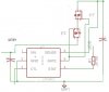
So, you appear to want a dual supply (Vbatt and Vin). Why not replace everything in the red outline with a diode. Thus the battery would go to diode anode (+), and the cathode ("bar" side) would go to the cathode of the diode from Vin. In other words, the diode from Vin (D11) does the same thing as this proposed new diode from the battery would do.
When Vin > Vbatt, then Vin will supply power to the rest of the circuit. When Vbatt > Vin or Vin is absent, then Vbatt will supply the power.
i have added those circuits to cut the battery supply when it is low, that is in the absence of the main supply vin,to prevent the complete drain out of battery if the mains is not connected .
OK, but you still only need one mosfet to shut down the battery when voltage is to low. The LTC4412 datasheet shows how that should be arranged.
Where are you getting the reference voltage for the comparator? A comparator and logic-level mosfet would be pretty simple.
Have you considered the LTC1998, which is a single package designed for this purpose? I am sure there are other devices that do the same. That part number was just the first to pop up.
This site uses cookies to help personalise content, tailor your experience and to keep you logged in if you register.
By continuing to use this site, you are consenting to our use of cookies.


")