Pankaj Khatri
New Member
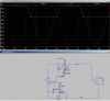
Can anyone tell me how this circuit is working?
I have taken this circuit from.. https://www.maximintegrated.com/cn/app-notes/index.mvp/id/760
I have taken this circuit from.. https://www.maximintegrated.com/cn/app-notes/index.mvp/id/760