Electro Tech is an online community (with over 170,000 members) who enjoy talking about and building electronic circuits, projects and gadgets. To participate you need to register. Registration is free. Click here to register now.
Welcome to our site! Electro Tech is an online community (with over 170,000 members) who enjoy talking about and building electronic circuits, projects and gadgets. To participate you need to register. Registration is free. Click here to register now.
Hi......
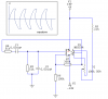
How to fine tune the output of the following oscillator?. Can I connect directly regulator circuit with the following circuit. From the experiment, it seems was a bad idea and the voltage output suddenly drop. Any suggestion are welcome....
Assuming you want to prevent the massive distortion shown on your graph?, you need to add some kind of automatic gain control in the feedback path. This is commonly done using a special (expensive!) thermistor or a cheap incandescent light bulb. It can also be done using a FET circuit, or (crudely) with diode clipping.
If you google for 'wien bridge oscillator' you will find plenty of information and many circuits.
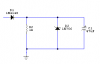
I think there is nothing wrong with my drawing. The output looks like that. BTW, the incandescent light you mean, any torchlight bulb will do? And I'm experimenting it with my own regulator ckt. check below..... :roll:
I don't really see the relevance of that?, what is it supposed to do?, and where does it connect?. A wien bridge oscillator is a VERY old and common circuit, with many examples you can download off the internet, why not use a 'proper' method?.
I need to build a cicuit to drive 2 motor. The speed of the 2nd motor dependent with the first motor. However I need to do some operation like comparator and etc. And to do this in analog domain I need AC signal, am I right? Then the oscillator is to serve that purpose. To drive motor, then I need to convert the AC signal into DC.
No, it has to be fairly specific, usually very low current bulbs are used.
As for the bulb, how about this **broken link removed**? Is it OK?
Let me clarify the output, the output is like capacitor charging and discharging with +ve and -ve side execpt it kind of distort (maybe the gain to high).
I need to build a cicuit to drive 2 motor. The speed of the 2nd motor dependent with the first motor. However I need to do some operation like comparator and etc. And to do this in analog domain I need AC signal, am I right?
Possibly, but I (yet again) suggest you simply get a circuit off the internet, which will specify whatever gain system it uses. But as you're not wanting any quality (wien bridge oscillators are commonly used for very low distortion sinewaves), a simple diode clipping type circuit would be nmore than good enough.
Let me clarify the output, the output is like capacitor charging and discharging with +ve and -ve side execpt it kind of distort (maybe the gain to high).
I have built this circuit and have found it to be more than good enough. I used polystyrene caps and ordinary resistors matched with a multimeter. It apparently uses a transistor as an AGC. That page explains a lot about how it works if nothing else, but I reccomend using the schematic so long as you don't need variable frequency.
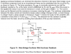
Texas Instruments has a pretty good applications note about many kinds of sine-wave oscillators. Their Wien bridge oscillator with a lightbulb for AGC has a serious error:
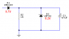
Your "regulator" is a wonderful circuit to short the output of your "oscillator".
When the output attempts to go more positive than 8.9V, both diodes conduct and short the output.
Texas Instruments has a pretty good applications note about many kinds of sine-wave oscillators. Their Wien bridge oscillator with a lightbulb for AGC has a serious error:
Is it? to continue, it seems the discussion is off topic. I think to start new thread after I became clear with my idea (maybe posting it with block diagram). BTW if I don't need to use oscillator, what else you suggesting? Anyway, thanks for the help....
You want one motor to control the speed of another motor?
Then you need the speeds of the motors to be sync'd. You can use a tachometer circuit from the 1st motor to control a speed control circuit for the 2nd motor.
An oscillator and regulator have nothing to do with it.
This site uses cookies to help personalise content, tailor your experience and to keep you logged in if you register.
By continuing to use this site, you are consenting to our use of cookies.

")