SeanHatch said:
Hmm I did not know anything about the minimum load of 2Kohms. I will have to fix things, then.
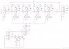
I tried that phase shift oscillator schematic you showed me a while ago, and I couldn't get it to work. It'd be nice if I could, though.
I've simulated the oscillator I have now in SPICE, using the uA741 subckt model I copied from my textbook. The results are pretty good (post filter), ill post some images tomorrrow. But, could the model be missing something that would mislead me?
Right now the output of the oscillator filter swings between -0.5 V and -2 V, which shouldn't short the FET, but is a pretty big sweep in regards to distortion; i think you told me this earlier.
do they make triple pot kind of things? i've never seen them.
Hi Sean,
Spice models certainly CAN mislead. And if you don't know to watch out, then it's probably typical that they mislead. I usually try to read datasheets carefully, do "sanity check" simulations, and breadboard early. I've seen opamp spice models that would happily pump out many amps of current, into a low-impedance load. Most real opamp outputs can only deal with 20 mA to 40 mA demands, at best. And most opamps don't do very well into even a 600-Ohm load. [I'll try simulating your oscillator in LTspice, to see what happens, tomorrow.]
Regarding your need for a triple-ganged pot: This might be one place where something like the H11F1M, or some Vactrols, might be expedient. You could use a single pot to set the LED current for several Vactrols or H11F1Ms (with their LEDS all in series), setting the resistances of their other terminals. (I don't know how well the Vactrols might track each other; probably good-enough, though.)
Alternatively, very low-tech: maybe you could mount three pots next to each other, and use string or twine to gang their shafts together, with multiple turns around each shaft before going to the next one.
Another alternative might be to motorize the pots. For "manual" control, you could do it with three small stepper motors and basically just a pulse generator (i.e. no computer needed, at least).
And you could also fairly-easily make one of several possible types of mechanical couplings, that would allow you to use just one DC or stepper motor to control all three pots. e.g. one threaded rod from motor, w/one worm gear on each pot shaft.
OR, to make it easy, if you use three identical pots, with values such that you only need about 1/3-turn of travel, then you could just attach an "arm" to each pot shaft and connect a mechanical link across all three arms' ends. Make all shafts co-axial and it could even be decent-looking and fairly nice to use.
- Tom Gootee
**broken link removed**