breakshift
Member
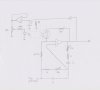
I've built the attached circuit diagram on a breadboard for prototyping. It's a variable frequency Wien Bridge oscillator with an automatic gain control circuit. A diode and cap on the output samples the peak output voltage and this is buffered and fed to a standard 5mm LED via a pot to vary its sensitivity. The LED is coupled to a light dependant resistor (via multiple layers of heat shrink) which acts to adjust the gain of the oscillator to control the output voltage.
The oscillator is built to vary between approximately 20kHz and 100kHz.
Op amps are TLC072 on a 5V regulated supply and bypassed by 10uF and 100nF caps.
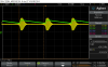
I initially used C=1uF and R=100k for the peak detect circuit. With these values the circuit oscillates fine but when I use the LED pot to increase sensitivity and thus reduce the output voltage below the op-amp supply rails, the oscillations go into a beating pattern. Screenshot of this attached with oscillations set to 15kHz. The yellow trace is the output and the green trace is the buffered output of the peak-detect capacitor.
I need the output amplitude to be less than the supply rails in order to reduce distortion on the sinusoid.
I'm trying to understand why this beating behaviour happens. I think its something to do with the RC time constant of the peak-detect circuit. Lowering the values of R and/or C seems to settle the oscillations. With C=100nF and R=10k I can reduce the output amplitude and get a nice clean sinusoid.
So the behaviour is related to values of R and C, but also depends on the frequency setting. To get stable oscillations at the higher frequencies I needed to reduce R and C further. So is it something to do with the time constant of the RC network and that of the output frequency?
If it's too high, perhaps it's too slow to react to changes in output amplitude and as a result can't really control it?
Any thoughts?
The oscillator is built to vary between approximately 20kHz and 100kHz.
Op amps are TLC072 on a 5V regulated supply and bypassed by 10uF and 100nF caps.
I initially used C=1uF and R=100k for the peak detect circuit. With these values the circuit oscillates fine but when I use the LED pot to increase sensitivity and thus reduce the output voltage below the op-amp supply rails, the oscillations go into a beating pattern. Screenshot of this attached with oscillations set to 15kHz. The yellow trace is the output and the green trace is the buffered output of the peak-detect capacitor.
I need the output amplitude to be less than the supply rails in order to reduce distortion on the sinusoid.
I'm trying to understand why this beating behaviour happens. I think its something to do with the RC time constant of the peak-detect circuit. Lowering the values of R and/or C seems to settle the oscillations. With C=100nF and R=10k I can reduce the output amplitude and get a nice clean sinusoid.
So the behaviour is related to values of R and C, but also depends on the frequency setting. To get stable oscillations at the higher frequencies I needed to reduce R and C further. So is it something to do with the time constant of the RC network and that of the output frequency?
If it's too high, perhaps it's too slow to react to changes in output amplitude and as a result can't really control it?
Any thoughts?