Continue to Site

Welcome to our site!

Electro Tech is an online community (with over 170,000 members) who enjoy talking about and building electronic circuits, projects and gadgets. To participate you need to register. Registration is free. Click here to register now.

  • Welcome to our site! Electro Tech is an online community (with over 170,000 members) who enjoy talking about and building electronic circuits, projects and gadgets. To participate you need to register. Registration is free. Click here to register now.

Orcad 9.2 simulation

Status
Not open for further replies.

andy257

Member
Hi Guys

Trying to use orcad to simulate some circuits and i am struggling to get anything to work.

Ive done some searching on here and found alot of questions relating to orcad.

If OPTIKON or STYX could offer their advice here that would be great as it appears you have some experience using this package from reading old posts.

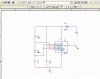
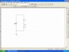
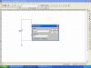
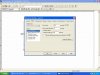
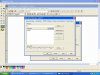
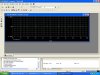
Basically i can build my schematic, start a new simulation, but i get no output at all. I place probe where i want to measure but the output is a flat line on zero volts.

I want to try and simulate a 555 timer but am unable to get an output. I tried a very very simple circuit to see if that would work and i get the same result.

I assume its my library files or something.

here are some photos to show where i am at and hopefully i can get soem help.

cheers

Andy
 

Attachments

  • circuit1_134.jpg
    circuit1_134.jpg
    109.5 KB · Views: 1,493
  • sim1_207.jpg
    sim1_207.jpg
    111.8 KB · Views: 1,165
  • simoptions.jpg
    simoptions.jpg
    120.4 KB · Views: 1,295
can anyone see where i am going wrong. This is a simle circuit just to try and figure out why its not working.

Thanks

Andy

sorry pics are not in order but you can get the general idea if you have used orcad before.
 

Attachments

  • libfiles.jpg
    libfiles.jpg
    121 KB · Views: 978
  • output_186.jpg
    output_186.jpg
    140.3 KB · Views: 995
Try to place a VSIN generator with AC = 0, DC = 0, VOFF = 0, VAMPL = 10, FREQ = 50 and you will see a sine wave.
 
thanks for the answers,

my main problem is to simulate a simple 555 timer (astable)

however this seems harder than it seems.

Has anyone ever simulated a 555 timer succesfully using ORCAD?????

thanks

Andy
 
Thanks Optikon greatful for your reply. Here is the output file as you suggested.


I get an output wave but its nothing like expected or what it should be.

Thanks

Andy
 

Attachments

  • 555_timer.txt
    4.2 KB · Views: 713
Hi Andy, post your schematic. If you don't have floating pins, then I think that you're using a Vdc as the power supply and that is not good for your circuit :)
 
eng1 said:
Hi Andy, post your schematic. If you don't have floating pins, then I think that you're using a Vdc as the power supply and that is not good for your circuit :)

That shouldnt be a problem? Other than it looks like it is at 0 VDC.
 
Yes its very strange why its not working. Seems odd that such a simple circuit cant be simulated.

i still hope its a silly mistake somewhere, sheeesh running out will power here.


here is the circuit for whoever asked for it.

YES i am using a VCD source, why is this bad??????????????

Andy
 

Attachments

  • 555_144.jpg
    555_144.jpg
    54.6 KB · Views: 1,682
Actually its working now and i have no idea how. I am using the demo verison at work where previously i have been using my own copy at home. So maybe something with lib files??? - i will check it out

I get my square wave output now at the correct frequency but i have noticed that the output voltage is only 1V???????

The timer is supplied from 5V

any suggestions?

Andy
 
Hi Andy, if you breadboard the circuit, it would work.
You should load pin3 with a 10k resistor, because you can't leave floating pins with SPICE.
Then, as I told you, the VDC generator is not good for this circuit.
In real oscillator circuits the oscillation starts because you turn the power on. With SPICE you must emulate that event. The voltage of your generator must be 0 at t=0 and then rise to 5 V. You can do this with a VPULSE generator. Place it instead of the VDC generator.
Set DC=0, AC=0, V1=0, V2=5, TD=10m, TR=100n=TF, PW=8s,
PER=10s.
For the Transient Analysis Setup, set Final time=5s (you will see 4 periods, since fo=1,1 Hz). Dont'care of the first period that is different because of the initial transient.
 
eng1 said:
Hi Andy, if you breadboard the circuit, it would work.
You should load pin3 with a 10k resistor, because you can't leave floating pins with SPICE.
Then, as I told you, the VDC generator is not good for this circuit.
In real oscillator circuits the oscillation starts because you turn the power on. With SPICE you must emulate that event. The voltage of your generator must be 0 at t=0 and then rise to 5 V. You can do this with a VPULSE generator. Place it instead of the VDC generator.
Set DC=0, AC=0, V1=0, V2=5, TD=10m, TR=100n=TF, PW=8s,
PER=10s.
For the Transient Analysis Setup, set Final time=5s (you will see 4 periods, since fo=1,1 Hz). Dont'care of the first period that is different because of the initial transient.

If startup is an issue, it is easier to just use an initial condition of a state that is opposite of what it starts up as.
 
hello , i was having a same problem that 555 astable circuits is not oscillicating in the pspice
can anyone giving advise to me
 
Last edited:
General Electronics Chat - 555 timer in orcad

two things you need to do to make the 555 timer work in orcad/pspice:
1. In your design, do not choose VCC for your power. Choose VDC instead. That's very important!
2. In your simulation settings, make sure that the box: Skip the initial transient bias point calculation is checked. (I'm using orcad 16.0)
Good luck.
 
Status
Not open for further replies.

Latest threads

New Articles From Microcontroller Tips

Back
Top