Mark_R
Member
Hi,
can't believe I'm struggling with this.
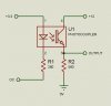
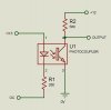
I'm trying to select an opto isolator to control 12vdc, the part under consideration is here --> https://www.electro-tech-online.com/custompdfs/2009/10/ps2801.pdf
The spec lists the Collector to Emitter Voltage as max 80V, Emitter to Collector Voltage as max 5V.
Am I interpreting correctly that;
1.- The 80v c to e voltage is max open circuit when the transistor is switched off and the collector is positive in relation to the emitter, the direction one would normally use it, (thus 12v would be fine) and
2.- The 5 volt e to c voltage is the maximum it can withstand reversed biased (emitter positive in relation to the collector) without letting out the factory smoke?
Thanks for the brain check.
can't believe I'm struggling with this.
I'm trying to select an opto isolator to control 12vdc, the part under consideration is here --> https://www.electro-tech-online.com/custompdfs/2009/10/ps2801.pdf
The spec lists the Collector to Emitter Voltage as max 80V, Emitter to Collector Voltage as max 5V.
Am I interpreting correctly that;
1.- The 80v c to e voltage is max open circuit when the transistor is switched off and the collector is positive in relation to the emitter, the direction one would normally use it, (thus 12v would be fine) and
2.- The 5 volt e to c voltage is the maximum it can withstand reversed biased (emitter positive in relation to the collector) without letting out the factory smoke?
Thanks for the brain check.
")