hello everyone,
i am a bit confused with some issues as i was experimenting on this circuit to understand it more.
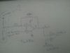
i am trying to get a very fine control of Vout from the error amp circuit shown and this Vout is fed to a comparator which then compares it with a triangle wave created using a TL084 opamp and fed to the inverting input if the comparator.
Anyway from the diagram i am using a gain of 10 and with a 5v(ideally it will be 4.5V) reference my problem is figuring out the right resistor values to give a range of input voltage into pin 2 of the error amp so as to have fine control of Vout assuming that the triangle wave starts from say 1.8V to 10V.
Think of it this way-imagine i replaced the whole error amp with just a 10k pot going into pin 3 of the LM393 comprator then i would have very smooth control of the PWM output,but with the error amp i cant quite get it so i am wondering what will be the range of input voltage to pin 2 of the error amp.
hope you get what i am trying to say. thanks.
i am a bit confused with some issues as i was experimenting on this circuit to understand it more.
i am trying to get a very fine control of Vout from the error amp circuit shown and this Vout is fed to a comparator which then compares it with a triangle wave created using a TL084 opamp and fed to the inverting input if the comparator.
Anyway from the diagram i am using a gain of 10 and with a 5v(ideally it will be 4.5V) reference my problem is figuring out the right resistor values to give a range of input voltage into pin 2 of the error amp so as to have fine control of Vout assuming that the triangle wave starts from say 1.8V to 10V.
Think of it this way-imagine i replaced the whole error amp with just a 10k pot going into pin 3 of the LM393 comprator then i would have very smooth control of the PWM output,but with the error amp i cant quite get it so i am wondering what will be the range of input voltage to pin 2 of the error amp.
hope you get what i am trying to say. thanks.