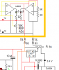
hi,It should be noted that I made an error in my description, the bridge PFETs are on when there is no torque which provides dynamic brake to stop bump steering and hold the steering in it's last position and then turned off prior to the NFET being turned on
Check this clip from your box circuit, is the 430R connected in series with that 10Kpot.?? because you are showing an LED in the same path.?
What are the OPA comps types.?
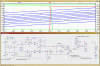
I have a working LTspice sim of the 'boxes' section and a the14v/8v/2.5v