Continue to Site

Welcome to our site!

Electro Tech is an online community (with over 170,000 members) who enjoy talking about and building electronic circuits, projects and gadgets. To participate you need to register. Registration is free. Click here to register now.

  • Welcome to our site! Electro Tech is an online community (with over 170,000 members) who enjoy talking about and building electronic circuits, projects and gadgets. To participate you need to register. Registration is free. Click here to register now.

An opamp question I can't make sense of

circuit975

New Member
Greetings to everyone,

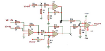
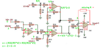
I found all values in an opamp question, but I couldn't find the Vout output value. How do we do the formulation?
I mean, with which formula will we calculate vout?


1720297592581.png
 
Something wacky as well, The NI input is at 3V, the Inv at 2V, so
D is not 2V, its 1V. The inputs draw very small currents, on the
order of 80 nA. So drop across R's negligible.

Diver300 is correct as the differential input of 1V is amped by the Aol
of the OpAmp, so its close to its + rail because of no FDBK. The Aol
typically 200,000. The output V swing is ~ 1V off its supply rail, so
Vout ~ 13V.


Regards, Dana.
 
What was the actual question?
The lines with the question marks is my best guess
How do we do the formulation?
I mean, with which formula will we calculate vout?
The OP is from Australia - the "make"/"do" is a generic placeholder for the specific verb most other regions would use. I'm assuming the OP is under 25. Older Australians start to use specific verbs.
 
Common sense tells me if pin 3 Vin+ = 3V and pin 2, Vin- = 2V
as a comparator, the output will be towards Vcc = 14V since it is open loop and Vin+ is higher.:cool:
 
Last edited:
I mean, with which formula will we calculate vout?
There is no "formula".
That question indicates you don't know how an op amp works.
Basically it's a differential amplifier with a very high differential gain (upwards of 100,000), so what would you think the output is for the differential input voltage you calculated?
 
Basically it's a differential amplifier with a very high differential gain (upwards of 100,000), so what would you think the output is for the differential input voltage you calculated?
Hint - the output ain't reaching 100k volts.
 
What was the actual question?
The lines with the question marks is my best guess

The OP is from Australia - the "make"/"do" is a generic placeholder for the specific verb most other regions would use. I'm assuming the OP is under 25. Older Australians start to use specific verbs.
Orijinal soruyu görmek isterseniz bu tam versiyondur;
1720333315868-png.146368


I may have said a missing point because I am just starting to learn opamps, sorry for that. I am trying to learn and understand

The point I am trying to understand is the vout calculation part at the end.
and +14 -14 v on the opamp, does that mean anything?
 

Attachments

  • 1720333315868.png
    1720333315868.png
    333.7 KB · Views: 278
The + and - 14 are to power the OpAmp.

A very basic model for the OpAmp looks like :

1720346328897.png


Where Rin very large, Rout very small, and G very large, like 50,000
or greater. The Vs+ and Vs- power its internal circuits, are normally referred
to as the rails, and limit what the OpAmp output can swing to.

So the equation is Vout = G x Vin = 50,000 x 1V = 50 kV. But OpAmps
do not generate power of V, they cannot swing beyond their power
rails, in our case no more than +14, no less than - 14. So OpAmp in that
case is no longer linear, do not follow our simple linear Vout equation.

1720346877247.png


Above simple internal model shows you output cannot go higher than Vcc or lower
than Vee, its supply rails.


Regards, Dana.
 
Do you know how to write equations for Kirchoff's Laws to solve for voltage drops?
This is a precursor. If you recognize patterns of R ratios to read the voltage ratio this helps to make shortcuts.

This last schematic is suspiciously flawed with a missing feedback R to make the circuit linear. Without this, the output must limited by the output towards either V+ or V- supply rail (14V) because even with a small difference on the input times a high gain (1e6 or a million) the output will not be linear and follow gain equations and "hit the rail" or upper or lower limits. So it acts like a comparator, but very slow with a 10 Hz internal compensation cap to make it unity gain stable. Read Wiki on Op Amps for some more details.

I added the voltages in green. Vin+ sets the common-mode voltage of both inputs when the negative feedback resistor operates in a linear mode. Linear mode means the output is well between V+ and V- using negative feedback and not limited.

1720459448598.png

If the missing R were equal to R14 = 2k and the inputs were reversed, then Vout = -3*1 + (-1/2)*(1+1) = -4

Any questions?

Daha iyi bir soru için her zaman tam detaylar önemlidir.
 

Attachments

  • 1720459124021.png
    1720459124021.png
    349.8 KB · Views: 84
Last edited:
It is not automatic that there is a missing R. The original design intent might be that O4 is acting as a comparator.

ak
Or a professor checking if the students understand the need for feedback - and what happens when there is no feedback.
 
Or a professor checking if the students can recognise:

An inverting amplifier
A non-inverting amplifier
A summing amplifier
A comparator

JimB
 
One of the giants in the early phase of OpAmp design and work. Excellent
reference, still quite useful.


Regards, Dana.
I have this book. As Dana mentioned, it is quite useful.
For the simple reason that Mr Frederiksen is able to explain arcane topics in a very straightforward manner.
As a matter of fact, the introduction, written by late legend Bob Pease, mentions that particular Mr Frederiksen’s talent.
 

Latest threads

New Articles From Microcontroller Tips

Back
Top