Continue to Site

Welcome to our site!

Electro Tech is an online community (with over 170,000 members) who enjoy talking about and building electronic circuits, projects and gadgets. To participate you need to register. Registration is free. Click here to register now.

  • Welcome to our site! Electro Tech is an online community (with over 170,000 members) who enjoy talking about and building electronic circuits, projects and gadgets. To participate you need to register. Registration is free. Click here to register now.

Opamp-assisted half H-bridge

Status
Not open for further replies.

Grossel

Well-Known Member
Hi

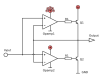
I'm have drawn a output stage as shown.

The obvious hatch with this circuit is that the transistors may get hot, unless both opamps has perfecly similar characteristics.

It's some year's I had opamps at school, but I do remember the basic.

I want to ensure that both transistors cannot conduct at same time. But I don't want to add low valued resistors on output to compensate.

What other methods can I use?

Thanks :)
 

Attachments

  • 2x-NPN_dualOpamp.png
    2x-NPN_dualOpamp.png
    13.6 KB · Views: 236
Hi,

Something looks wrong with the op amp polarities...both transistors turn on at the same time. We dont usually use op amps for driving bridge transistors anyway as they are too slow unless you use very fast ones which is a waste anyway. We use transistors to drive the bridge transistors or special driver IC's.
 
You can use a single opamp and complementary transistors at the output. This is the ultimate ClassB stage. Note that the current in the transistors Q1 & Q2 is essentially leakage only when the input is at zero V. I took the liberty of running it on split supplies.

Purists will say that it will have some crossover distortion, but that is the price for having nearly zero quiescent current. Note the little dance the output of the opamp does V(oa) green trace as the signal crosses the middle.

ps. you can make R1 zero Ω, and that reduces the cross-over distortion a bit... The sim was done at 10kHz. If you use an opamp with a slew rate of several V per us, I'll bet that if you used this as an audio amp, most folks wouldn't hear the distortion...
 

Attachments

  • DF64.jpg
    DF64.jpg
    162.2 KB · Views: 189
  • DF64a.jpg
    DF64a.jpg
    75.4 KB · Views: 183
Last edited:
Hi,

Something looks wrong with the op amp polarities...both transistors turn on at the same time. We dont usually use op amps for driving bridge transistors anyway as they are too slow unless you use very fast ones which is a waste anyway. We use transistors to drive the bridge transistors or special driver IC's.
Hi. I know that it's the common way. It's not supposed to be fast, and I'm just curious about this.

The amplifier I posted a schematic for can be compared to a set of two voltage followers connected together, where one of them can only drain current and the other one can only surge current. That's why the polarity seems so weird, because the use of Q2 (as a NPN opposed to a PNP transistor) the opamps have to be inverted to each other.

[edit]
You can use a single opamp and complementary transistors at the output. This is the ultimate ClassB stage. Note that the current in the transistors Q1 is essentially leakage only when the input is at zero V. I took the liberty of running it on split supplies.

Purists will say that it will have some crossover distortion, but that is the price for having nearly zero quiescent current. Note the little dance the output of the opamp does V(oa) green trace as the signal crosses the middle.
Thanks. I remember this from schol, had lab on this very circuit.

I'm not very concern about crossover distortion. It's more important to use only NPN transistors and make an amplifier that works.
I also know I've seen an amplifier output stage that contains a pair of NPN's, but there was also a smaller PNP there as I can remember. But it's not relevant here.
 
Last edited:
Your original circuit has a quiescent current 0f several amps...
 
Your original circuit has a quiescent current 0f several amps...
Yes, I assumed that. Thanks for updating me on certain english terms :)

Therefor I get back to my original question. How to modify this circuit so it can be tuned so that the quiescent current ≈zero?
 
...Therefor I get back to my original question. How to modify this circuit so it can be tuned so that the quiescent current ≈zero?

How about this? Check out Ie(Q1) purple and Ic(Q3) lt. blue. I(R3) is the load current (sum of the previous two).
 

Attachments

  • DF64b.jpg
    DF64b.jpg
    174.6 KB · Views: 180
How about this? Check out Ie(Q1) purple and Ic(Q3) lt. blue. I(R3) is the load current (sum of the previous two).
That is a good idea. I see
that Q2 and Q3 together will roughly behave like a pair of PNP darlington coupled transistors.

But, a little PNP transistor is as I can see a better/cheaper solution than hving to choose a matching pair of NPNP/PNP :)
 
what you have just drawn is a simplified gatedrive, ensuring the Transistors saturate ASAP for turn-on and turn-off.

as for protecting against shootthough there is a very simple circuit you can use.
R-C-D + schmitt to delay the turn-on edge while ensuring the turn-off edge is still fast.
 
what you have just drawn is a simplified gatedrive, ensuring the Transistors saturate ASAP for turn-on and turn-off.

as for protecting against shootthough there is a very simple circuit you can use.
R-C-D + schmitt to delay the turn-on edge while ensuring the turn-off edge is still fast.

With any reasonable slew rate of the opamp, shoot through is not a problem. It takes a finite time for V(b) to slew across that middle region, during which neither part of the totem-pole is on. Put another way, one turns off before the other turns on, naturally.
 
Last edited:
Thanks a lot for giving me reasonable alternatives. But I go ahead and twist my head a little more to get out some possible solution. Sorry I have to be that stubborn, but I won't give up the idea of making it without any PNP transistors.
The first Idea I came up with is to just put in a constant current source and a low value resistor to bias Opamp2 so that it will turn on at a little higher voltage (because feedback now "lie" about the actual output voltage).
 

Attachments

  • 2x-NPN_dualOpamp_ProMet1.png
    2x-NPN_dualOpamp_ProMet1.png
    28.7 KB · Views: 172
Last edited:
Status
Not open for further replies.

Latest threads

New Articles From Microcontroller Tips

Back
Top