Continue to Site

Welcome to our site!

Electro Tech is an online community (with over 170,000 members) who enjoy talking about and building electronic circuits, projects and gadgets. To participate you need to register. Registration is free. Click here to register now.

  • Welcome to our site! Electro Tech is an online community (with over 170,000 members) who enjoy talking about and building electronic circuits, projects and gadgets. To participate you need to register. Registration is free. Click here to register now.

OpAmp Adder x2

Status
Not open for further replies.
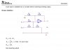
I have a sensor to which I need two outputs, Sensor*10 + 0.5 and Sensor*10 + 0.2. I applied the gain in the first stage and then add the 0.5 and 0.2 in a second stage.

My initial thought is below:
Opamp Dual Adder.jpg

By just looking at it I see a whopper resistor network. Resistors R1, R2, R7, R8, R9, R12, R13, and R14 are all tied together. I have isolated the pot for tuning the 0.2V and 0.5V source using a voltage follower, but I'm wondering if I also need to isolate the output of U1 from R8 and R13.
 
The value from the wiper to ground could be very low, the wiper will be set to 0.2V and 0.5V. Easily less than 2k and 5k respectively.

A negative value out doesn't mean anything. I was looking at the 'direct addition' arrangement; non-inverting.

Do you forsee an issue with the resistors mentioned connected as drawn, interfering with their respective jobs? For example, R1/2 set the gain for U1, but will the gain in that section be impacted by the fact that R8/9 and R13/14 are connected to ground. Or will the direct addition resistors for U4 affect the gain/output for U5 and vise versa?
 

Attachments

  • direct addition.jpg
    direct addition.jpg
    42.1 KB · Views: 189
The value from the wiper to ground could be very low, the wiper will be set to 0.2V and 0.5V. Easily less than 2k and 5k respectively.

A negative value out doesn't mean anything. I was looking at the 'direct addition' arrangement; non-inverting.

Do you forsee an issue with the resistors mentioned connected as drawn, interfering with their respective jobs? For example, R1/2 set the gain for U1, but will the gain in that section be impacted by the fact that R8/9 and R13/14 are connected to ground. Or will the direct addition resistors for U4 affect the gain/output for U5 and vise versa?

I wouldn't even consider doing it that way, use a 'real' adder circuit, which is inverting - use one of the surplus opamps to invert it back if need be, as you don't need the buffers on the pots - it will also save on un-needed resistors.
 
There is no negative supply. I have been told I have +12V but I haven't found one in the schematics yet. I have found +24V. This circuit is to adapt a existing flow sensor to work with a new fan controller. The old fan controller had the setpoints set internally, the new one has the setpoints as analog inputs. Hence adding the voltage to the sensor reading. As it is I need to keep this as small as possible to fit within the existing enclosure. Adding another power supply is not going to be an option.

I'm open to suggestions, but it all has to stay positive.
 
What is the total voltage range of the sensor signal? (e.g., 0.1V to 0.3V)
 
What is the total voltage range of the sensor signal? (e.g., 0.1V to 0.3V)

Close! The actual sensor output is 0.1 to 0.7V, but the fan controller is expecting 10 times that. The input on the fan controller is 0 to 10 volts, but below 1V the controller interprets as not-running.
 
Close! The actual sensor output is 0.1 to 0.7V, but the fan controller is expecting 10 times that. The input on the fan controller is 0 to 10 volts, but below 1V the controller interprets as not-running.

Ok, how much load can the sensor drive? Can it drive 47K?

What reference voltage do you want to use? Your supply is either 12V or 24V, but likely not stable enough to reference your offset voltage to?
 
Assuming your sensor can drive 47k, here is a three-opamp, single-supply solution. To work properly, the 12V supply must be dead on (just like your original circuit). If it is critical, you should use a proper 12.00V voltage reference. If the sensor cannot drive the 47K input, then use one more opamp section as a voltage follower.

The plots show the voltage at node a, b, and c vs the sensor input voltage.
 

Attachments

  • DF81b.jpg
    DF81b.jpg
    278.5 KB · Views: 189
That's an interesting solution.

It doesn't address the concern of my original circuit. Would or does the resistor networks of the direct adders and gain section impact each other when connected like that?
 
Hi,

You can create a summing junction with resistors alone if the two voltages to be added connect to two higher value resistors and the summing resistor is significantly lower in value. For example, two 100k resistors and one 1k resistor would create an adder with only a small error.

Here is a circuit based on that concept using one op amp with a slight variation because one voltage is always small. This can be modified to produce any output offset so only one op amp per output is required. The voltage reference V2 only has to power a large impedance >500k so it can power several such circuits so that we can have as many outputs as we need. So this means two op amps for two outputs.

A note about resistor R6:
R6 is only there to show it's significance in the circuit. Of course it can be combined with R1 to create a single resistor R1 who's value is the parallel resistance of the real R6 and the original R1. For example, with R1=10k and R6=500k that would make the required value of R1 equal to
9.804k but 9.8 would work as well, and possibly even 10k would be ok with a little more error in the offset, and then R6 itself is left out of the circuit.

In the drawing, the equation in black is the full equation for the circuit while the blue equation at the bottom assumes R1 is the parallel combination of R1 and R6, so they are both the same equation one is just simpler because we can parallel R1 and R6 to make it simpler.

The value of R5 is shown as 500k along with the design formula for any new R5 you wish to calculate based on the value of the reference voltage V2. If V2 is made to be 10v instead of 1.0v then resistor R5 has to increase by 10 times (5M) and so does R6. Since R6 would then be so big it probably would not have to be considered any more, as the parallel combo of R1 and R6 would then come out to 9.980k, but it's up to you. If you use 1 percent resistors you may want to do that.

In any case you should test this circuit (or any other) once it is built because the input offset voltage affects the output offset to some degree. This could be unfavorable if you are looking for decent accuracy. So maybe pick an op amp with low offset and low offset drift for better results. You may also want to trim the offsets to get them more close to what you want.

Typical output with zero voltage input without trimming: 0.195v
Typical output with 1.000 volts input without trimming: 10.195v
 

Attachments

  • PositiveOffsetWithPositiveSupplyOnly-1.gif
    PositiveOffsetWithPositiveSupplyOnly-1.gif
    11 KB · Views: 202
Last edited:
OK that gives me one output. So I would need to double the circuit and make sure the gains between the two are the same. That sounds a bit rough.

I understand that most of you don't like my concept. But would it work? I see that it is op amp heavy, but tuning and adjusting each stage would be independent (at least as I see the circuit). I should be able to adjust the input thresholds without affecting the gain of the adder circuit. but will the gain of the sensor input opamp be dependent on the direct adder, or will each of the direct addition stages be dependent on the other? Does the sensor input gain stage need to be isolated from the direct adder resistor network?
 
Hello again,

A bit rough? Tuning and adjusting each stage would be independent, so they could be tuned quite well. Using 1 percent resistors would probably do it unless you are looking for super duper accuracy, in which case we would need to talk more anyway.
 
I'm not worried about each stage within the layout you propose, as all of the "math" is integrated to within a single block. But when I duplicate the layout to form the second half of the circuit, I need to have the same gain and same error in both stages.

MikeAl dual.jpg

Then my concern and question will be the same as my circuit. Will the 0.5V stage interfere/affect the 0.2V stage when the second stage is added as depicted? (sorry about the duplicated numbers, I just did a mspaint copy/paste)

Is the consensus that the three stages in my original circuit in post #1 will be independent of each other and the resistor networks will not interfere with each other and I should go ahead and send for prototyping? Or is my gut feeling right, the networks will affect each other and I need to add two voltage followers to isolate the networks.
 
Hello again,

Yes you want the same gain in both stages, but that is exactly the same case as in your original circuit in post #1.

In fact, both circuits are almost the same except the one in post #1 uses 5 op amp sections while the one you redrew in post #14 requires only 2 sections.

So our circuits are not too much different except you are buffering your pots (reference voltages) and buffering the input.

The question comes up do you really need to buffer the sensor with an extra op amp section?
Also, if the 12v line is stable in post #1 then you can replace the op amps that buffer the pots with just pots and a resistor. But in either case the resistor has to be a larger value to ensure that the network adds ok and does not require super tiny reference voltages.
If the input signal resistor is 10k and the reference resistor is 10k, then the reference voltage needs to be very very small on the order of 0.012 volts. But if the reference resistor is 50k, then the reference voltage can be 1v or something like that. If the reference resistor is 500k (as in my schematic) then you can use a reference voltage of around 10 volts. So you see how this works.
And the other stage requires a different resistor (R5 in my schematic).
Also, note that since your network is the same except for the buffers, you can also use the idea that the signal resistor (R1 in mine) starts out at 10k but reduces to 10k in parallel with R5 (in mine) and that gives you the value you want for R1 (in mine).

No the two stages will not interfere with each other because of the resistor networks.

The equation for your circuit is the same as for my circuit (as shown in my schematic) so you can use that as a guide. The equation does not take into account the input offset of the op amps so you need to adjust the reference voltage as you originally planned anyway. A low input offset op amp would be a good idea anyway though and if it is low enough you might even be able to build this without requiring adjustments, depending on the desired accuracy (which you havent stated yet BTW).

Here your drawing showing the equivalent resistor numbers. The numbers in blue refer to my schematic.
The design formulas are the same but i changed R1="R2 in parallel with R5" to make it simpler to state the relationship between R1 and R5 (or R6). So if R2 is 10k (typical value) and R5 is 500k then R1=10k in parallel with 500k which is 9.8k, so R1=9,8k.
 

Attachments

  • OpampDualAdder2b.gif
    OpampDualAdder2b.gif
    89.6 KB · Views: 177
Last edited:
MrAl,

I spent the say working with you circuit on the breadboard and could not get the fan controller to work properly. It would start based on the threshold and then speed up to maximum. In the process I noticed the speed reading on the controller dropping. I then realized the sensor input drops as the speed increases because Va in post #9 is inverted.

Question on impedances for the various networks.
directadd_nobuffer.jpg

The resistor network to set the lower threshold (add 0.2V) forms a resistor divider where the upper resistor totals 118K and the lower totals 2K (or a 11.8 : 0.2 ratio). The resistor values directly from the direct adder application note are 10k and 20k. How much difference in impedance is needed between the threshold network and the adder network? Should I be looking to increase or decrease the 2k resistor and/or the 10k/20k resistors?

In short, how far apart do R29 and R30 need to be? I can then adjust all of the other resistors values based on that.
 
Last edited:
Hi again,

In theory that circuit probably works because the equation works out to the right values. However, for practical reasons it would be better to change R30 to something like 100k instead of 10k. What this does is helps prevent us from having to adjust the pot to a very low value voltage which does not play well with any input offset present in the op amp. A higher 'reference' voltage (at the arm of the pot) is preferable, and that simply requires a higher value for R30. So with R30=100k that means we are looking at a 2v output from the pot arm terminal, or thereabouts. Because that changed though that means we need less gain in the last stage (as you have pictured as the second op amp). To get the new gain we would solve an equation with different input values, and for R30=100k it comes out to a gain of 2.1 which means R34 should be equal to 11k (so that 11/10+1=2.1).
Also, because we need a higher reference voltage now that means R28 has to come down to something like 8k. That will allow us to adjust the pot arm for 2v output with a 12v supply voltage.

In case you want to try some other values, here is the equation for Vout with your new circuit:
Vout=(G*(vref*R31+Vin*A*R30)*R32)/(R31*R32+R30*R32+R30*R31)

where
G is the gain of the first stage (equal to 10),
A is the gain of the last stage (equal to 3 in your circuit or 2.1 with the modified 100k circuit),
vref is the voltage adjusted at the pot arm.

What you would do with this equation is enter in all the known values of R like R31 and R32, enter in the new value of R30 (like 100k) and then simplify. Once simplified, solve for the new gain G and the new reference voltage vref using values of Vin of 0 and 1 and a value of 0 for vref and the known required outputs with the respective Vin values. For example, if vref were equal to zero then Vout must equal 10.000 for Vin equal to 1.000 (that's without an offset).

Note that the reference voltage vref for this example was set to equal around 2 volts. For the higher offset version, you'll have to be able to adjust the pot arm up above 7 volts for a 0.7v offset. That means either a bigger pot value or a smaller value for R28 for that version.

If you wish to check out a particular set of values to see how the pot adjustment affects the output, you can use this equation:
Code:
Vout=(G*R32*(Vs*R2*R31^2*R32+Vin*A*R2*R30*R31*R32+Vs*R2*R30*R31*R32+Vin*A*R1*R30*R31*R32+Vin*A*R2*R30^2*R32+Vin*A*R1*R30^2*R32+Vin*A*R1*R2*R30*R32+Vs*R2*R30*R31^2+Vin*A*R2*R30^2*R31+Vin*A*R1*R30^2*R31+Vin*A*R1*R2*R30*R31))/((R31*R32+R30*R32+R30*R31)*(R2*R31*R32+R1*R31*R32+R2*R30*R32+R1*R30*R32+R1*R2*R32+R2*R30*R31+R1*R30*R31+R1*R2*R31))

where
Vs is the source voltage,
R1 is the upper pot resistance added to the upper pot fixed resistor (R28),
R2 is the lower pot resistance,
A is the first stage gain,
G is the last stage gain

This is a rather large equation but it includes the effects of 'loading' of the pot on the network. It can be used to show that once the gains are set right and the pot is adjusted to the right offset, the output works exactly as required, and that means 0.2v output for 0v input and 10.2v output for 1.00v input and everything in between has the same offset of 0.2 volts.
You could also use this equation to investigate problems due to resistor tolerances.
 
Last edited:
Although I had not actually calculated the values, I had contemplated doing just what you mentioned. Using more range from the pot and then correspondingly reducing the gain of the second stage, which had the added benefit of moving higher into the operating range of the opamp and away from the power rails.

If I wanted to implement the circuit as shown, how large would R30 (and corresponding adjusted R31-34) need to be such that chance in the impedance of the pot lower leg (what I indicated as R29) would not be factor? Would increasing all resistors x5 be enough (R30 10k->50k with R29=2k)?
 
Hi again,

If you change R30 to 100k that should be good enough because like i said that increases the adjusted voltage at the pot to about 10 times the previous value. But the gain of the second stage then has to be 2.1 instead of 3.

The effect of the pot impedance only affects the *calculated* values, not the *measured* values. In other words, if you set the pot to zero ohms (on the bottom) and input to 1.000 volts you can check the first stage gain by measuring the output of that stage. It should be exactly 10 volts. Then set the gain of the second stage to get 10 volts out there too.
Then set Vin=0 and set the pot to provide 0.2 volts output. This might require a rail to rail output op amp or some tricks for a lower cost op amp. Then check with Vin=1.000 to see 10.200 volts on the output.

So dont worry about the pot too much, just set it based on what you get at the very output not really at the pot arm. When i quote values at the pot arm i mean approximate values not exact values (like 0.2) because with the extra pot resistance we need a voltage at the arm that is slightly over 0.2 or 0.7 not those exact voltages. For example, when you see 0.2 volts on the output that means the pot arm voltage is really 2.026 or thereabouts, but you dont need to know that, just what the output is. This is with 100k for R30 as mentioned before.
So when you adjust the reference pot measure the output, not the value at the pot arm.
 
I think we are passing each other on the meanings. If I bump R30 to 100K, then I will bump R31, R32, and R33 to 100K and R34 to 200K. With the lower leg resistance at 2k for 0.2V and 5K for 0.5V (the other stage required), they seem awfully close to the resistances used within the opamp networks. In other 'recent' designs/discussions, that has been an issue because they setup resistor divider networks that were supposed to be high impedance sources. I just don't want to fall into the same trap.
 
Status
Not open for further replies.

Latest threads

New Articles From Microcontroller Tips

Back
Top